Steam
 From Citizendium - Reading time: 7 min

Geothermal power plant in Iceland
Steam is the vapor (gaseous) phase of water (H2O) usually generated by the boiling of water. When the steam does not contain any liquid water, it is known as dry steam and it is completely colorless. However, when the steam contains tiny droplets of condensed liquid water, it appears to the eye as a white cloud (see the steam being vented from a geothermal power plant in the adjacent photograph).
What is very often referred to as smoke from cooling towers and other vents in industrial facilities is water vapor which has partially condensed and is mistaken to be white smoke. Water aerosols and mists, such as those created by spray cans for misting house plants or certain types of humidifiers, may also create small visible clouds of water droplets, but aerosols, mists and fogs are not steam. Liquids other than water may also form visible clouds when vaporized, but they are not clouds of steam.
Steam is manufactured in industrial processes by the boiling and vaporization of liquid water. It also occurs naturally by being vented from volcanoes, fumaroles, geysers and other geothermal sources.
Steam has a great many industrial and domestic uses. Probably the most important and by far the largest use of steam is in nuclear, fossil fuel and geothermal power plants.
Types of steam[edit]

As shown in the adjacent diagram, there are three types of steam:
- Wet steam: A mixture of water plus steam (liquid plus vapor) at the boiling point temperature of water at a given pressure. Quality of steam refers to the fraction or percentage of gaseous steam in a wet steam mixture.
- Dry steam: Steam, at the given pressure, that contains no water (also referred to as saturated steam). The steam quality = 100%. At the top of steam generator units for producing saturated steam, there are moisture separators used to remove residual water droplets from outgoing steam.
- Superheated steam: Dry steam, at the given pressure, that has been heated to a temperature higher than the boiling point of water at that pressure.
Referring to the adjacent drawing again, water is converted into wet, dry saturated or superheated steam in three steps:
- Water at point 1 is heated to its boiling point at the given pressure of point 2 (the dark blue line). At that point the water is then referred to as saturated water. The amount of heat added between points 1 and 2 is called sensible heat.
- The water is further heated at constant pressure (the red isobar from point 2 to point 3) to form wet steam. When it is completely vaporized (at point 3), it is then dry saturated steam. The amount of heat required to completely vaporize the water is called the heat of vaporization and denoted as Hv or Hvap.
- The dry saturated steam is yet further heated at constant pressure (the red isobar from point 3 to point 4). The steam is then referred to as superheated steam. The amount of heat added to superheat the dry saturated steam is also called sensible heat.
- It should be noted that the points 2 and 3 are at the same boiling point temperature and pressure and also that, at those conditions, the liquid and the steam (whether wet or dry) are in equilibrium with each other.
Production[edit]
Ways of producing steam from water include use of boilers or steam generators. Boilers are pressure vessels in which water is heated to produce pressurized steam, for generally heating houses or buildings, for steam engines, or a variety of other uses. Steam generators are devices or units, often including boilers (the definitions coincide greatly), for producing (generating) steam for power plant, industrial, or other uses. The size of steam generators ranges from bench top to very large units or sections of a thermal power plant. In the field of nuclear power plants, the term steam generator refers specifically to a particular very large heat exchanger used to thermally connect the primary (reactor plant) system to a secondary (steam plant) system in a pressurized water reactor (PWR) plant, which generates steam for the steam plant, of course.
Uses[edit]
Electricity generation[edit]
The worldwide capacity of electrical power generation by conventional coal-fired power plants currently amounts to about 800,000 MW[1][2][3][4] and the worldwide capacity of nuclear power generation amounts to about 370,000 MW.[5][6] That amounts to a total of 1,170,000 MW of worldwide generation, most of which involves the use of superheated steam to drive the turbines that spin the electrical generators (see the adjacent schematic diagram).[7]
Assuming an overall thermal efficiency of 34%, a steam generator (boiler) efficiency of 75 to 85% and an electrical generator efficiency of 98.5%, a conventional coal-fired power plant would use superheated steam at a rate of 3.47 to 3.93 (t/h) per MW of power output. Thus, a 1000 MW power plant would use 3,470 to 3,930 metric tons (tonnes) of steam per hour and the steam used by the 1,170,000 MW of worldwide power generation by coal-fired and nuclear power plants might be as much as 4,000,000 to 4,600,000 metric tons of steam per hour.
The diagrams below schematically depict the equipment used in a conventional fuel-fired steam to electric power plant as well as the temperature-entropy (T-S) diagram of the corresponding Rankine cycle. A nuclear power plant differs only to the extent that the heat required by the boiler is provided by heat derived from a nuclear reactor.
 |
 Diagram of a power plant coal-fired steam generator |
 |
Cogeneration of heat and power[edit]
Cogeneration is also referred to as combined heat and power or CHP. In electrical power generation, the turbine exhaust steam is typically condensed and returned to the boiler for re-use. However, in one form of cogeneration, all or part of the turbine exhaust steam is distributed through a district heating system to heat buildings rather than being condensed. The world's biggest steam cogeneration system is the district heating system which distributes steam from seven cogeneration plants to provide heating for 100,000 buildings in the city of New York.[8][9]
Steam engines[edit]
As an overall definition, a steam engine is an engine that uses steam to perform mechanical work. By that definition, steam turbines are steam engines. However, this section describes steam engines that use the expansion of steam to move a piston that performs work. Such steam engines were the driving force behind the Industrial Revolution of the 18th century and gained widespread commercial use for driving machinery in factories, powering water pumping stations and transport application such as railway locomotives, steamships and road vehicles. The use of tractors driven by steam engines led to an increase in the land available for agricultural cultivation.
Although largely replaced by steam turbines, stationary reciprocating steam engines are still used in industry and elsewhere for driving pumps, gas compressors and other types of machinery.
Uses in industrial process facilities[edit]
A great many processes in petroleum refineries, natural gas processing plants, petrochemical plants and other industrial facilities use steam as:
- A heat source in heat exchangers designed to increase the temperature of distillation column feedstocks.
- A heat source for distillation column reboilers.
- A heat source injected directly into various distillation columns known as steam strippers and side-cut strippers to provide the required distillation heat.
- The motive force for steam turbines that are used directly to drive large compressors and centrifugal pumps.
- The motive force for injectors and ejectors.
- A heat source for stripping the spent catalyst in fluid catalytic cracking processes of volatile hydrocarbons.
- A medium for purging of process vessels such as petroleum coke drums in delayed coking units.
- A reactant in catalytic steam-methane reformers for the industrial production of hydrogen.
- A diluent in steam cracking units which produce petrochemical feedstocks such as ethylene and other olefins from natural gas and petroleum hydrocarbons such as methane, ethane, propane, butanes, petroleum naphtha and petroleum gas oil.
- The heat source for evaporation processes in sugar refining and in water desalination processes.
- A heat source flowing through tubular coils installed inside storage tanks to heat certain stored liquids.
Other uses[edit]
- Sterilization
- An autoclave, which uses steam under pressure, is used in microbiology laboratories and similar environments for sterilization; autoclaving is also a major method for industrial and home canning of food
- Agricultural
- In agriculture, steam is used for soil sterilization to avoid the use of harmful chemical agents and increase soil health.
- Commercial and domestic uses
- Steam's capability to transfer heat is also used in the home as well as commercial facilities for pressure cookers, steam cleaning of fabrics and carpets, steam ironing and for heating of buildings.
- Ship propulsion
- Steam is sometimes used to power steam turbines to propel naval ships, ice breakers, and other ships; steam turbines are primarily used in nuclear-powered ships, with other new construction using various combinations of gas turbines, diesel engines, and electric motors
Steam tables and Mollier diagrams[edit]
Steam tables provide tabulated thermodynamic data for the liquid and vapor phases of water. The table below is only an example of the type of data provided. In a complete set of steam tables, the table would provide data in temperature increments of 1 °C. The complete steam tables would also provide a similar "Saturated Steam:Pressure Table" in which the first column would have pressure values and the second column would be temperature values. Most steam tables include tabulated thermodynamic data for superheated steam as well.
| T °C |
P bar |
P kPa |
ρL kg/m3 |
ρV kg/m3 |
HL J/g |
HVap J/g |
HV J/g |
SL J/(g·K) |
SVap J/(g·K) |
SV J/(g·K) |
|---|---|---|---|---|---|---|---|---|---|---|
| 10 | 0.012282 | 1.2282 | 999.65 | 0.00941 | 42.02 | 2477.2 | 2519.2 | 0.15109 | 8.7487 | 8.8998 |
| 20 | 0.023393 | 2.3393 | 998.19 | 0.01731 | 83.91 | 2453.5 | 2537.4 | 0.29648 | 8.3695 | 8.6660 |
| 30 | 0.042470 | 4.2470 | 995.61 | 0.03042 | 125.73 | 2429.8 | 2555.5 | 0.43675 | 8.0152 | 8.4520 |
| 40 | 0.073849 | 7.3849 | 992.18 | 0.05124 | 167.53 | 2406.0 | 2573.5 | 0.57240 | 7.6831 | 8.2555 |
| 50 | 0.12352 | 12.352 | 988.00 | 0.08315 | 209.34 | 2381.9 | 2591.3 | 0.70381 | 7.3710 | 8.0748 |
| 100 | 1.0142 | 101.42 | 958.35 | 0.5982 | 419.17 | 2256.4 | 2675.6 | 1.3072 | 6.0469 | 7.3541 |
| 150 | 4.7616 | 476.16 | 917.01 | 2.5481 | 632.18 | 2113.7 | 2745.9 | 1.8418 | 4.9953 | 6.8371 |
| 200 | 15.549 | 1554.9 | 864.66 | 7.8610 | 852.27 | 1939.7 | 2792.0 | 2.3305 | 4.0996 | 6.4302 |
| 250 | 39.762 | 3976.2 | 798.89 | 19.967 | 1085.8 | 1715.2 | 2800.9 | 2.7935 | 3.2785 | 6.0721 |
| 300 | 85.879 | 8587.9 | 712.14 | 46.168 | 1345.0 | 1404.6 | 2749.6 | 3.2552 | 2.4507 | 5.7059 |
| Symbols: P = absolute pressure ρL = liquid density ρV = vapor density | ||||||||||
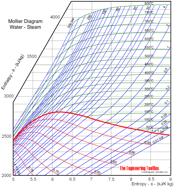
Mollier diagrams are graphical representations of the thermodynamic properties of materials involving "Enthalpy" as one of the coordinates. Mollier diagrams are named after Richard Mollier (1863 - 1935), a professor at Dresden University in Germany, who pioneered the graphical display of the relationship of temperature, pressure, enthalpy, entropy and volume of steam (as well as for moist air) that has aided in the teaching of thermodynamics to many generations of engineers. His enthalpy-entropy (H-S) diagram for steam was first published in 1904.[11][12]
Mollier diagrams are routinely used to visualize the working cycles of thermodynamic systems involved with the chemical engineering process design of power plants (fossil or nuclear), gas compressors, steam turbines, refrigeration systems and air conditioning.
A sample Mollier diagram for steam is presented below and others are available online:[13][14][15]

Mollier H-S Diagram for Water-Steam
References[edit]
- ↑ A megawatt (MW) of electrical power is often denoted as MWe to differentiate it from other forms of power.
- ↑ International Energy Agency, 2006, Key Energy Statistics (International Energy Agency)
- ↑ International Energy Outlook 2008; Highlights (Energy Information Administration, U.S. DOE)
- ↑ International Energy Outlook 2008: Chapter 5 (Energy Information Administration, U.S. DOE)
- ↑ Energy, Electricity and Nuclear Power Estimates for the Period up to 2030 2009 Edition, International Atomic Energy Agency
- ↑ Nuclear Power Plants, Worldwide European Nuclear Society
- ↑ The amount would be even larger if power plants using other fuels were included (i.e., fuel oil, natural gas and biomass, wood, etc).
- ↑ Steam Carl Bevelhymer, Gotham Gazette, November 10, 2003
- ↑ Newsroom: Steam From the website of the Con Edison company in New York.
- ↑ NISTIR 5078, Thermodynamic Properties of Water Tabulation from the IAPWS Formulation 1995 for the Thermodynamic Properties of Ordinary Water Substance for General and Scientific Use (1998), Allan H. Harvey, National Institute of Standards and Technology
- ↑ Mollier Charts From the website of the ChemicaLogic Corporation
- ↑ R. K. Rajput (2009). Engineering Thermodynamics, 3rd Edition. Jones & Bartlett. ISBN 1-934015-14-8. Google Books Use the search function for "Mollier diagram" and select page 77.
- ↑ Mollier diagram of water-steam From the website of Engineering ToolBox
- ↑ H-S Diagram for Water Associate Professor Israel Urieli, Department of Mechanical Engineering, Ohio University.
- ↑ Mollier Diagram for Water and the excellent animation video at Mollier Diagram for Water
 EncycloReader
is supported by the
EncycloReader
is supported by the