Strike and dip
Topic: Earth
 From HandWiki - Reading time: 9 min


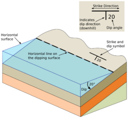
In geology, strike and dip is a measurement convention used to describe the plane orientation or attitude of a planar geologic feature. A feature's strike is the azimuth of an imagined horizontal line across the plane, and its dip is the angle of inclination (or depression angle) measured downward from horizontal.[1] They are used together to measure and document a structure's characteristics for study or for use on a geologic map.[2] A feature's orientation can also be represented by dip and dip direction, using the azimuth of the dip rather than the strike value. Linear features are similarly measured with trend and plunge, where "trend" is analogous to dip direction and "plunge" is the dip angle.[3]
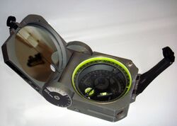
Strike and dip are measured using a compass and a clinometer. A compass is used to measure the feature's strike by holding the compass horizontally against the feature. A clinometer measures the features dip by recording the inclination perpendicular to the strike.[1] These can be done separately, or together using a tool such as a Brunton transit or a Silva compass.
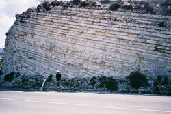
Any planar feature can be described by strike and dip, including sedimentary bedding, fractures, faults, joints, cuestas, igneous dikes and sills, metamorphic foliation and fabric, etc. Observations about a structure's orientation can lead to inferences about certain parts of an area's history, such as movement, deformation, or tectonic activity.[3]
Elements
When measuring or describing the attitude of an inclined feature, two quantities are needed. The angle the slope descends, or dip, and the direction of descent, which can be represented by strike or dip direction.[4]
Dip
Dip is the inclination of a given feature, and is measured from the steepest angle of descent of a tilted bed or feature relative to a horizontal plane.[5][6] True dip is always perpendicular to the strike. It is written as a number (between 0° and 90°) indicating the angle in degrees below horizontal. It can be accompanied with the rough direction of dip (N, SE, etc) to avoid ambiguity.[1] The direction can sometimes be omitted, as long as the convention used (such as right-hand rule) is known.[3]
A feature that is completely flat will have the same dip value over the entire surface. The dip of a curved feature, such as an anticline or syncline, will change at different points along the feature and be flat on any fold axis.[1]
Strike
Strike is a representation of the orientation of a tilted feature. The strike line of a bed, fault, or other planar feature, is a line representing the intersection of that feature with a horizontal plane. The strike of the feature is the azimuth (compass direction) of the strike line.[5] This can be represented by either a quadrant compass bearing (such as N25°E), or as a single three-digit number in terms of the angle from true north (for example, N25°E would simply become 025 or 025°).[3][1]
A feature's orientation can also be represented by its dip direction. Rather than the azimuth of a horizontal line on the plane, the azimuth of the steepest line on the plane is used.[3] The direction of dip can be visualized as the direction water would flow if poured onto a plane.[7]
Apparent dip

While true dip is measured perpendicular to the strike, apparent dip refers to an observed dip which is not perpendicular to the strike line. This can be seen in outcroppings or cross-sections which do not run parallel to the dip direction.[7] Apparent dip is always shallower than the true dip.[1] If the strike is known, the apparent dip or true dip can be calculated using trigonometry:
where δ is the true dip, α is the apparent dip, and β is the angle between the strike direction and the apparent dip direction, all in degrees.[8]
Trend and plunge
The measurement of a linear feature's orientation is similar to strike and dip, though the terminology differs because "strike" and "dip" are reserved for planes. Linear features use trend and plunge instead. Plunge, or angle of plunge, is the inclination of the feature measured downward relative to horizontal. Trend is the feature's azimuth, measured in the direction of plunge. A horizontal line would have a plunge of 0°, and a vertical line would have a plunge of 90°.[3][7] A linear feature which lies within a plane can also be measured by its rake (or pitch). Unlike plunge, which is the feature's azimuth, the rake is the angle measured within the plane from the strike line.[3]
Maps and cross-sections
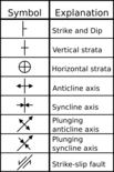
On geologic maps, strike and dip can be represented by a T symbol with a number next to it. The longer line represents strike, and is in the same orientation as the strike angle. Dip is represented by the shorter line, which is perpendicular to the strike line in the downhill direction. The number gives the dip angle, in degrees, below horizontal, and often does not have the degree symbol. Vertical and horizontal features are not marked with numbers, and instead use their own symbols. Beds dipping vertically have the dip line on both sides of the strike, and horizontal bedding is denoted by a cross within a circle.[2][9]
Interpretation of strike and dip is a part of creating a cross-section of an area. Strike and dip information recorded on a map can be used to reconstruct various structures, determine the orientation of subsurface features, or detect the presence of anticline or syncline folds.[1][2]
Measurement
Conventions
There are a few conventions geologists use when measuring a feature's azimuth. When using the strike, two directions can be measured at 180° apart, at either clockwise or counterclockwise of north. One common convention is to use the "right-hand rule" (RHR) where the plane dips down towards the right when facing the strike direction, or that the dip direction should be 90° clockwise of the strike direction. However, in the UK, the right-hand rule has sometimes been specified so that the dip direction is instead counterclockwise from the strike. Some geologists prefer to use whichever strike direction is less than 180°. Others prefer to use the "dip-direction, dip" (DDD) convention instead of using the strike direction. Strike and dip are generally written as 'strike/dip' or 'dip direction,dip', with the degree symbol typically omitted. The general alphabetical dip direction (N, SE, etc) can be added to reduce ambiguity. For a feature with a dip of 45° and a dip direction of 75°, the strike and dip can be written as 345/45 NE, 165/45 NE, or 075,45. The compass quadrant direction for the strike can also be used in place of the azimuth, written as S15E or N15W.[1][3]
Tools

Strike and dip are measured in the field using a compass and with a clinometer. A compass is used to measure the azimuth of the strike, and the clinometer measures inclination of the dip.[2] Dr. E. Clar first described the modern compass-clinometer in 1954, and some continue to be referred to as Clar compasses.[10] Compasses in use today include the Brunton compass and the Silva compass.
Smartphone apps which can make strike and dip measurements are also available, including apps such as GeoTools. These apps can make use of the phone's internal accelerometer to provide orientation measurements. Combined with the GPS functionality of such devices, this allows readings to be recorded and later downloaded onto a map.[11]
When studying subsurface features, a dipmeter can be used. A dipmeter is a tool that is lowered into a borehole, and has arms radially attached which can detect the microresistivity of the rock. By recording the times at which the rock's properties change across each of the sensors, the strike and dip of subsurface features can be worked out.[12]
References
- ↑ 1.0 1.1 1.2 1.3 1.4 1.5 1.6 1.7 "Measuring dip and strike". 2019-02-01. https://www.geological-digressions.com/how-to-measure-dip-and-strike/.
- ↑ 2.0 2.1 2.2 2.3 Panchuck, Karla (2018). Measuring Geological Features. https://openpress.usask.ca/physicalgeology/chapter/13-5-measuring-geological-structures/.
- ↑ 3.0 3.1 3.2 3.3 3.4 3.5 3.6 3.7 Waldron, John; Snyder, Morgan (2020). Orientation of Structures. Open Education Alberta. https://openeducationalberta.ca/introductorystructuralgeology/chapter/b-orientation-of-structures/.
- ↑ Lahee, Federic H (1961) (in en). Field Geology (1 ed.). New York: McGraw-Hill. pp. 6. ISBN 9780070358089. https://archive.org/details/fieldgeology00lahegoog/page/6/mode/2up.
- ↑ 5.0 5.1 Tarbuck, Edward J; Lutgens, Frederick K (2005) (in en). Earth: An Introduction to Physical Geology (8 ed.). Upper Saddle River, N.J.: Pearson / Prentice Hall. pp. 308. https://archive.org/details/earthintroductio00tarb/page/308/mode/2up.
- ↑
 "Dip". New International Encyclopedia. 1905.
- ↑ 7.0 7.1 7.2 Lisle, Richard J (2004) (in en). Geological Structures and Maps - A Practical Guide (3 ed.). pp. 2–6. https://www.researchgate.net/publication/329934024.
- ↑ "How to calculate an apparent dip from a real dip (and viceversa) using orthographic projection and trigonometry". 2012-05-01. http://www.structuralgeology.org/2012/05/how-calculate-apparent-dip-real-dip.html.
- ↑ "Digital Cartographic Standard for Geologic Map Symbolization". FGDC Geological Data Subcommittee. USGS. 2017-05-09. http://ngmdb.usgs.gov/fgdc_gds/index.php.
- ↑ Clar, E (1954). "Ein zweikreisiger Geologen- und Bergmannskompaß zur Messung von Flächen und Linearen.". Verhandlungen der Geologischen Bundesanstalt 4. https://archive.org/details/verhandlungen-der-geologischen-bundesanstalt.
- ↑ Weng Y.-H., Sun F.-S. & Grigsby J.D. (2012). "GeoTools: An android phone application in geology". Computers & Geosciences 44: 24–30. doi:10.1016/j.cageo.2012.02.027. Bibcode: 2012CG.....44...24W.
- ↑ "The Dipmeter Tool". Kansas State University. 2017-03-24. https://www.kgs.ku.edu/Publications/Bulletins/LA/13_dipmeter.html.
Further reading
- Compton, Robert R. (1985). Geology in the Field. New York: J. Wiley and Sons. ISBN 978-0-471-82902-7. OCLC 301031779. https://books.google.com/books?id=3U4SAQAAIAAJ&q=editions:0DEedUPzlsf0WMItwQI.
 |
 KSF
KSF

