Electronic circuit simulation
 From HandWiki - Reading time: 4 min
Electronic circuit simulation uses mathematical models to replicate the behavior of an actual electronic device or circuit. Simulation software allows for modeling of circuit operation and is an invaluable analysis tool. Due to its highly accurate modeling capability, many colleges and universities use this type of software for the teaching of electronics technician and electronics engineering programs. Electronics simulation software engages its users by integrating them into the learning experience. These kinds of interactions actively engage learners to analyze, synthesize, organize, and evaluate content and result in learners constructing their own knowledge.[1]
Simulating a circuit’s behavior before actually building it can greatly improve design efficiency by making faulty designs known as such, and providing insight into the behavior of electronics circuit designs. In particular, for integrated circuits, the tooling (photomasks) is expensive, breadboards are impractical, and probing the behavior of internal signals is extremely difficult. Therefore, almost all IC design relies heavily on simulation. The most well known analog simulator is SPICE. Probably the best known digital simulators are those based on Verilog and VHDL.

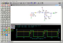
Some electronics simulators integrate a schematic editor, a simulation engine, and on-screen waveform display (see Figure 1), allowing designers to rapidly modify a simulated circuit and see what effect the changes have on the output. They also typically contain extensive model and device libraries. These models typically include IC specific transistor models such as BSIM, generic components such as resistors, capacitors, inductors and transformers, user defined models (such as controlled current and voltage sources, or models in Verilog-A or VHDL-AMS). Printed circuit board (PCB) design requires specific models as well, such as transmission lines for the traces and IBIS models for driving and receiving electronics.
Types
While there are strictly analog[2] electronics circuit simulators, popular simulators often include both analog and event-driven digital simulation[3] capabilities, and are known as mixed-mode or mixed-signal simulators if they can simulate both simultaneously.[4] An entire mixed signal analysis can be driven from one integrated schematic. All the digital models in mixed-mode simulators provide accurate specification of propagation time and rise/fall time delays.
The event driven algorithm provided by mixed-mode simulators is general-purpose and supports non-digital types of data. For example, elements can use real or integer values to simulate DSP functions or sampled data filters. Because the event driven algorithm is faster than the standard SPICE matrix solution, simulation time is greatly reduced for circuits that use event driven models in place of analog models.[5]
Mixed-mode simulation is handled on three levels; (a) with primitive digital elements that use timing models and the built-in 12 or 16 state digital logic simulator, (b) with subcircuit models that use the actual transistor topology of the integrated circuit, and finally, (c) with In-line Boolean logic expressions.
Exact representations are used mainly in the analysis of transmission line and signal integrity problems where a close inspection of an IC’s I/O characteristics is needed. Boolean logic expressions are delay-less functions that are used to provide efficient logic signal processing in an analog environment. These two modeling techniques use SPICE to solve a problem while the third method, digital primitives, use mixed mode capability. Each of these methods has its merits and target applications. In fact, many simulations (particularly those which use A/D technology) call for the combination of all three approaches. No one approach alone is sufficient.
Another type of simulation used mainly for power electronics represent piecewise linear[6] algorithms. These algorithms use an analog (linear) simulation until a power electronic switch changes its state. At this time a new analog model is calculated to be used for the next simulation period. This methodology both enhances simulation speed and stability significantly.[7]
Complexities
Process variations occur when the design is fabricated and circuit simulators often do not take these variations into account. These variations can be small, but taken together can change the output of a chip significantly.
Temperature variation can also be modeled to simulate the circuit's performance through temperature ranges.[8]
See also
References
- ↑ "Disadvantages and Advantages of Simulations in Online Education". http://e-articles.info/e/a/title/Disadvantages-and-Advantages-of-Simulations-in-Online-Education/.
- ↑ Mengue and Vignat, Entry in the University of Marne, at Vallee
- ↑ Fishwick, P. "Entry in the University of Florida". https://www.cise.ufl.edu/~fishwick/introsim/paper.html.
- ↑ Pedro, J; Carvalho, N. "Entry in the Universidade de Aveiro, Portugal". http://dragao.co.it.pt/conftele2001/proc/pap006.pdf.
- ↑ L. Walken and M. Bruckner, Event-Driven Multimodal Technology
- ↑ Pejovic, P.; Maksimovic, D. (May 13, 1995). "A new algorithm for simulation of power electronic systems using piecewise-linear device models". IEEE Transactions on Power Electronics 10 (3): 340–348. doi:10.1109/63.388000. Bibcode: 1995ITPE...10..340P. https://ieeexplore.ieee.org/document/388000.
- ↑ Allmeling, J.H.; Hammer, W.P. (July 13, 1999). "PLECS-piece-wise linear electrical circuit simulation for Simulink". Proceedings of the IEEE 1999 International Conference on Power Electronics and Drive Systems. PEDS'99 (Cat. No.99TH8475). 1. pp. 355–360 vol.1. doi:10.1109/PEDS.1999.794588. ISBN 0-7803-5769-8. https://ieeexplore.ieee.org/document/794588.
- ↑ Ohnari, Mikihiko (1998). Simulation engineering. Ohmsha. ISBN 9784274902178. https://books.google.com/books?id=azmLQG_SOAUC&dq=%22Electronic+circuit+simulation%22+temperature+variation&pg=PA177. Retrieved October 12, 2022.
External links
- WCCA Simple Comparing of different Methods
- Electronic circuit simulation at the Open Directory Project
 |
 KSF
KSF