Distributed element circuit
Topic: Engineering
 From HandWiki - Reading time: 19 min
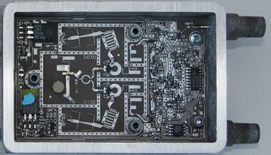
Distributed element circuits are electrical circuits composed of lengths of transmission lines or other distributed components. These circuits perform the same functions as conventional circuits composed of passive components such as capacitors, inductors, and transformers. They are used mostly at microwave frequencies where conventional components are difficult or impossible to implement.
A major advantage of distributed element circuits is that they can be produced cheaply as a printed circuit board for consumer products such as satellite television. They are also made in coaxial and waveguide formats for applications such as radar, satellite communication, and microwave links.
A phenomenon that is much used in distributed element circuits is that a length of transmission line can be made to behave as a resonator. Distributed element components that do this include stubs, coupled lines, and cascaded lines. Circuits built from these components include filters, power dividers, directional couplers, and circulators.
Distributed element circuits were investigated in the 1920s and 1930s but did not become important until World War II when they were used in radar. After the war their use was at first limited to military, space, and broadcasting infrastructure use but improvements in materials science in the field soon led to wider applications.
Circuit modelling
Distributed element circuits are those circuits designed using the distributed element model. This model is an alternative to the lumped element model in which the passive electrical elements of electrical resistance, capacitance and inductance are assumed to be "lumped" at one point in space in, respectively, a resistor, capacitor or inductor lumped component. The distributed element model is used when this assumption no longer holds and those quantities are considered to be distributed in space. The assumption breaks down when there is a significant time taken for electromagnetic waves to travel from one terminal of the component to the other. Significant in this context is a time in which a noticeable phase change has occurred. The amount of phase change is very much dependent on the frequency or wavelength of the wave. A common rule of thumb amongst engineers is to change from the lumped to the distributed model when distances involved are more than one-tenth of a wavelength (36° phase change). In any case, the lumped model completely fails at one-quarter wavelength (90° phase change) with entirely incorrect results. Due to this dependence on wavelength, the distributed element model is used mostly at the higher frequencies, at low frequencies distributed element components are too bulky. Distributed designs become feasible above 300 MHz and are the technology of choice at microwave frequencies above 1 GHz.[1]
There is no clear-cut demarcation in the frequency at which these models should be used. The changeover is usually somewhere in the range 100 to 500 MHz but the scale of the technology being used is significant. Miniaturised circuits can continue to use the lumped model to a higher frequency. Printed circuit boards (pcbs) using through-hole technology are larger than an equivalent design using surface-mount technology. Hybrid integrated circuits are smaller than pcb technologies and monolithic integrated circuits are smaller than both. Hence, integrated circuits can use lumped designs at higher frequencies than printed circuits and this is done in some radio frequency integrated circuits. The choice is particular significant for hand-held devices because lumped element designs generally result in a smaller product.[2]
Construction with transmission lines
The overwhelming majority of distributed element circuits are composed of lengths of transmission line. This is a particularly simple form to model. The cross-sectional dimensions of the line are unvarying along its length and are chosen to be small compared to the signal wavelength, thus, distribution along the length of the line only need be considered. Such an element of a distributed circuit is entirely characterised by its length and characteristic impedance. A further simplification occurs in commensurate line circuits where all the elements are made the same length. With commensurate circuits, a lumped circuit design prototype consisting of capacitors and inductors can be directly converted into a distributed circuit with one-to-one correspondence between the elements of the lumped circuit and the distributed circuit.[3]
Commensurate line circuits are important because they have an established design theory. Circuits consisting of arbitrary lengths of transmission line, or even arbitrary shapes, do not. An arbitrary shape can certainly be analysed with Maxwell's equations to determine its behaviour but finding useful structures is a matter of trial and error, or guesswork.[4]
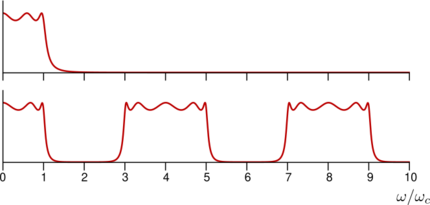
An important difference between distributed element circuits and lumped element circuits is that the frequency response of a distributed circuit periodically repeats as shown in the Chebyshev filter example, whereas the equivalent lumped circuit does not. This is a result of the transfer function of lumped forms being a rational function of complex frequency whereas distributed forms are an irrational function. Another difference is that cascade connected lengths of line introduce a fixed delay at all frequencies (assuming an ideal line). There is no equivalent in lumped circuits for a fixed delay, although an approximation could be constructed over a limited frequency range.[5]
Advantages and disadvantages
Distributed element circuits are cheap and easy to manufacture in some formats, but take up more space than lumped element circuits. This is problematic in mobile devices, especially hand-held ones, where space is at a premium. If the operating frequencies are not too high, the designer may choose to go down the route of miniaturising components rather than switching to distributed elements. On the other hand, parasitic elements and resistive losses in lumped components are greater with increasing frequency as a proportion of the nominal value of the lumped element impedance. In some cases designers may choose to go to a distributed element design, even if lumped components are available at that frequency, in order to benefit from the improved quality. Distributed element designs tend to have greater power handling capability. With a lumped component, all the power being passed by the circuit is concentrated in a small volume.[6]
Media
Paired conductors
There are many forms of transmission line and any of them can be used to construct distributed element circuits. The historically earliest, and still most widely used, form is a pair of conductors. The most common form of paired conductors is twisted pair as used for telephone lines and internet connections. This is not commonly used for distributed element circuits because the signal frequencies used on these cables are lower than the point where distributed element designs become advantageous. However, designers frequently start with a lumped element design and then convert it into an open-wire distributed element design. Open wires are a pair of parallel uninsulated conductors, for instance as used for telephone lines on telegraph poles. The designer does not usually intend to implement the circuit in this form, it is merely an intermediate step in the design process. Distributed element designs with conductor pairs are limited to a few specialist uses such as Lecher lines and the twin-lead used for antenna connections.[7]
Coaxial
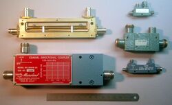
Coaxial line, a centre conductor surrounded by a shielding conductor, is widely used for interconnecting units of microwave equipment. It is also used for longer distance transmissions. Manufacture of coaxial distributed element devices was common in the second half of the 20th century. However, these types in many applications have been replaced by planar forms due to cost and size considerations. Air dielectric coaxial is used for low-loss and high-power applications. It is still common for distributed element circuits in other media to transition to a coaxial connector at the circuit ports.[8]
Planar
The majority of modern distributed element circuits use planar transmission lines, especially those in mass-produced consumer items. There are several forms of planar line, but the kind known as microstrip is the most common. It can be manufactured by the same process as printed circuit boards and hence is cheap to make. It also lends itself to integration with lumped circuits on the same board. Other forms of printed planar lines include stripline and finline and many variations. Planar lines can also be used in monolithic microwave integrated circuits where they are integral to the device chip.[9]
Waveguide
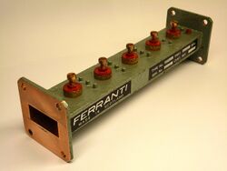
Many of the distributed element designs can be directly implemented in waveguide. However, there is an additional complication with waveguides in that multiple modes are possible. These sometimes exist simultaneously and this situation has no analogy in conducting lines. Waveguides have the advantages of lower loss and higher quality resonators over conducting lines, but their relative expense and bulk means that microstrip is often preferred. Waveguide mostly finds uses in high-end products such as high-power military radars and the upper microwave bands where planar formats are too lossy. Waveguide becomes bulkier with lower frequency which militates against its use in the lower bands.[10]
Mechanical
In a few specialist applications such as the mechanical filters in high-end radio transmitters (marine, military, amateur radio) electronic circuits can be implemented as mechanical components. This is done largely because of the high quality of the mechanical resonators. They are used in the radio frequency band below microwave frequencies where waveguides might otherwise be used. Mechanical circuits too can be implemented, in whole or in part, as distributed element circuits. The frequency at which the transitions to distributed element design becomes feasible or necessary are much lower with mechanical circuits. This is because the speed signals travel through mechanical media is much lower than the speed of electrical signals.[11]
Circuit components
There are several structures that are repeatedly used in distributed element circuits. Some of the common ones are described below.
Stub
A stub is a short length of line that branches to the side of a main line. The end of the stub is often left open- or short-circuited but may also be terminated with a lumped component. A stub can be used on its own, for instance for impedance matching, or several of them can be used together in a more complex circuit such as a filter. A stub can be designed as the equivalent of a lumped capacitor, inductor, or resonator.[12]
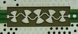
Departures from constructing with uniform transmission lines in distributed element circuits are rare. One such departure that is widely used is the radial stub which is shaped like a sector of a circle. They are often used in pairs, one either side of the main transmission line. Such pairs are called butterfly or bowtie stubs.[13]
Coupled lines
Coupled lines are two transmission lines between which there is some electromagnetic coupling. The coupling can be direct or indirect. In indirect coupling the two lines are run closely together for a distance with no screening between them. The strength of the coupling depends on the distance between the lines and the cross section presented to the other line. In direct coupling, branch lines directly connect the two main lines together at intervals.[14]
Coupled lines are a common method of constructing power dividers and directional couplers. Another property of coupled lines is that they act as a pair of coupled resonators. This property is used in many distributed element filters.[15]
Cascaded lines
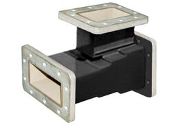
Cascaded lines are lengths of transmission line where the output of one line is connected to the input of the next. Multiple cascaded lines of different characteristic impedances can be used to construct a filter or a wide-band impedance matching network. This is called a stepped impedance structure.[16] A single cascaded line one quarter of a wavelength long forms a quarter-wave impedance transformer. This has the useful property of transforming any impedance network into its dual. In this role it is called an impedance inverter. This structure can be used in filters to implement a lumped element prototype in ladder topology as a distributed element circuit. The quarter-wave transformers are alternated with some kind of distributed element resonator to achieve this. However, this is now a dated design and more compact inverters such as the impedance step are used instead. An impedance step is the discontinuity formed at the junction of two cascaded transmission lines of different characteristic impedance.[17]
Helical resonator
Helical resonators consist of a helix of wire in a cavity. One end is unconnected and the other is bonded to the cavity wall. Although superficially similar to a lumped inductor, helical resonators are, in fact, a distributed element component and are used in the VHF and lower UHF bands.[18]
Circuit blocks
Filters and impedance matching
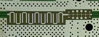
Filters form a major part of the circuits constructed with distributed elements. There is a very wide range of structures used for constructing filters. These include stubs, coupled lines and cascaded lines. Variations of these themes include interdigital filters, combline filters and hairpin filters. Many filters are constructed in conjunction with dielectric resonators.[19] More recent developments include fractal filters.[20]
As with lumped element filters, the more elements that are used, the closer the filter comes to an ideal response and the structure can become quite complex.[21] On the other hand, for simple narrowband requirements just a single resonator may suffice such as a single stub or a spurline filter.[22]
Impedance matching for narrow-band applications is frequently achieved with a single matching stub. However, for wide-band applications the impedance matching network takes on a definite filter-like design. The designer starts by prescribing the required frequency response and designs a filter with that response. The only difference from a standard filter design is that the source and load impedances of the filter differ.[23]
Power dividers, combiners and directional couplers
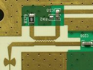
A directional coupler is a four-port device that couples power flowing in one direction only from one path to another. Two of the ports are the input port and output port of the main line. A proportion of the power entering the input port is coupled to a third port, called the coupled port. None of the power entering the input port is coupled to the fourth port, usually called the isolated port. For power flowing in the reverse direction and entering the output port, a reciprocal situation occurs. Some of the power is coupled to the isolated port, but none is coupled to the coupled port.[25]
Power dividers are often constructed as a directional coupler with the isolated port permanently terminated in a matched load making them effectively a three-port device. There is no essential difference between the two devices. The term directional coupler tends to be used when the coupling factor (the proportion of power reaching the coupled port) is low and power divider when the coupling factor is high. A power combiner is simply a power splitter used in reverse. In distributed element implementations using coupled lines, indirectly coupled lines are more suitable for low-coupling directional couplers and directly coupled branch line couplers are more suitable for high-coupling power dividers.[26]
Distributed element designs rely on the length of the elements being one-quarter wavelength (or some other length). This will only be true at one particular frequency. Simple designs thus have a limited bandwidth over which they will work successfully. As with impedance matching networks, a wide-band design requires multiple sections and the design starts to take on a filter-like form.[27]
Hybrids

A directional coupler that splits power equally between the output and coupled ports (a 3 dB coupler) is called a hybrid.[28] The term hybrid originally referred to a hybrid transformer, a lumped device used in telephones, but now has a wider meaning. A widely used distributed element hybrid that does not fall into the category of coupled lines is the hybrid ring or rat-race coupler. Each of the four ports is connected to a ring of transmission line at different points. It works by waves travelling in opposite directions around the ring setting up standing waves. At some points on the ring, destructive interference results in a null and no power will leave a port set at that point. At other points, constructive interference maximises the power transferred.[29]
Another way of using a hybrid coupler is to produce the sum and difference of two signals. The diagram shows a hybrid ring being used in this way. The two input signals are fed into the ports marked as 1 and 2. The sum of the two signals appears at the port marked as Σ and the difference at the port marked as Δ.[30]
Besides their use as couplers and power dividers, directional couplers can be used in balanced mixers, frequency discriminators, attenuators, phase shifters, and antenna array feed networks.[31]
Circulator
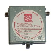
A circulator is usually a 3-port or 4-port device in which power entering one port is transferred to the next port in rotation as if round a circle. Power can only flow in one direction around the circle (clockwise or anticlockwise) and no power is transferred to any of the other ports. Most distributed element circulators are based on ferrite materials.[32]
Uses of circulators include using as an isolator to protect a transmitter or other equipment from damage due to reflections from the antenna, and a duplexer connecting antenna, transmitter and receiver of a radio system.[33]
An unusual application of a circulator is in a reflection amplifier where the negative resistance of a Gunn diode is used to reflect back more power than it received. The circulator is used to direct the input and output power flows to separate ports.[34]
Passive circuits, both lumped and distributed, are nearly always reciprocal. Circulators are an exception to this. There are several ways to define or represent reciprocity. A convenient one for circuits at microwave frequencies (where distributed element circuits are used) is in terms of their S-parameters. A reciprocal circuit will have an S-parameter matrix, [S], that is symmetric. From the definition of a circulator it is clear that this will not be the case;
for an ideal 3-port circulator. Thus circulators must be non-reciprocal by definition. This also means that it is impossible to build a circulator from standard passive components, either lumped or distributed. The presence of the ferrite, or some other non-reciprocal material or system, is essential for the device to work.[35]
Active components
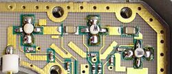
Distributed elements are passive elements, but most applications will require active components in some role. A microwave hybrid integrated circuit uses distributed elements for many passive components, but active components such as diodes and transistors, and some passive components, are discrete. The active components may be packaged, or they may be placed on the substrate in chip form without any individual packaging to reduce their size and eliminate the packaging parasitics.[36]
Distributed amplifiers consist of a number of amplifying devices, usually FETs, with all their inputs connected via one transmission line, and all their outputs via another transmission line. The lengths of the two lines must be equal between each transistor for the circuit to work correctly. Each transistor adds to the output of the amplifier. This is different from a conventional multistage amplifier where the gain is multiplied by the gain of each stage. A distributed amplifier thus has lower gain than a conventional amplifier with the same number of transistors. However, it has significantly greater bandwidth. In a conventional amplifier, the bandwidth is reduced by each additional stage. In a distributed amplifier the overall bandwidth is the same as the bandwidth of a single stage. Distributed amplifiers are used when a single large transistor, or a complex multi-transistor amplifier would be too large to treat as a lumped component. The linking transmission lines serve to separate the individual transistors.[37]
History

Distributed element modelling was first used in electrical network analysis by Oliver Heaviside[38] in 1881. Heaviside used this to find a correct description of the behaviour of signals on the transatlantic telegraph cable. Transmission of early transatlantic telegraph had been difficult and slow due to an effect now called dispersion but this was not well understood at the time. Heaviside's analysis, now referred to as the telegrapher's equations, identified the problem and suggested[39] methods for overcoming it. This is still the standard analysis of transmission lines.[40]
Warren P. Mason was the first to investigate the possibility of distributed element circuits. He filed a patent[41] in 1927 for a coaxial filter designed by this method. Mason and Sykes published the definitive paper on the method in 1937. Mason was also the first to suggest a distributed element acoustic filter in his 1927 doctoral thesis, and a distributed element mechanical filter in a patent[42] filed in 1941. In fact, the acoustic work had come first and as a result of it Mason's colleagues at Bell Labs in the Radio Department requested him to assist with coaxial and waveguide filters.[43]
Mason's work was concerned with the coaxial form and other conducting wires, although much of it could also be adapted for waveguide. Prior to World War II there was not much call for distributed element circuits. The frequencies chosen for radio transmissions at the time were always lower than the point at which distributed elements became advantageous. This was due to lower frequencies having a greater range, a primary consideration for broadcast purposes. This all changed with the wartime requirements for radar. There was a surge in distributed element filter development (an essential component of radars) and the technology was extended from the coaxial domain into the waveguide domain.[44]
The wartime work was mostly not published until after the war for secrecy reasons. This made it difficult to disentangle who exactly was responsible for each development. An important centre for this research was the MIT Radiation Laboratory (Rad Lab), but work was also undertaken elsewhere in the US and Britain. The Rad Lab work was published[45] by Fano and Lawson.[46] Another wartime development was the hybrid ring. This work was carried out at Bell Labs and was published[47] after the war by W. A. Tyrrell. Tyrrell describes hybrid rings implemented in waveguide and analyses them in terms of the well known waveguide magic tee. However, other researchers[48] soon published coaxial versions of this device.[49]
George Matthaei led a research group at Stanford Research Institute that included Leo Young. The group was responsible for many filter designs. Matthaei himself first described the interdigital filter[50] and the combline filter.[51] The group's work was published[52] in a landmark book in 1964 covering the state of distributed element circuit design at that time. It remained a major reference work for many years.[53]
Planar formats started to take off with the invention of stripline by Robert M. Barrett. Stripline was another wartime invention, but the details were not published[54] until 1951. Microstrip, invented in 1952,[55] became a commercial rival to stripline. However, planar formats did not start to become widely used in microwave applications until better dielectric materials became available for the substrates in the 1960s.[56] Another structure that had to wait for better materials was the dielectric resonator. Its advantages of compact size and high quality were first pointed out[57] by R. D. Richtmeyer in 1939. However, materials with good temperature stability were not found until the 1970s. Dielectric resonator filters are now common in both waveguide and transmission line filters.[58]
On the theoretical front, an important development was the commensurate line theory of Paul I. Richards published[59] in 1948. Kuroda's identities, an important set of transforms that allowed many designs to be practically implemented, were provided[60] by Kuroda in 1955.[61]
References
- ↑ Vendelin et al., pp. 35–37
- ↑
- Nguyen, p. 28
- Vendelin et al., pp. 35–36
- ↑ Hunter, pp. 137–138
- ↑ Hunter, p. 137
- ↑ Hunter, pp. 139–140
- ↑
- Doumanis et al., pp. 45–46
- Nguyen, pp. 27–28
- ↑
- Gurdeep et al., pp. 178–179
- Magnusson et al., p. 240
- Gupta, p. 5.5
- Craig, pp. 291–292
- Henderson & Camargo, pp. 24–25
- Chen et al., p. 73
- ↑
- Natarajan, 11–12
- ↑ Ghione & Pirola, pp. 18–19
- ↑ Ghione & Pirola, p. 18
- ↑
- Taylor & Huang pp. 353–358
- Johnson (1983), p. 102
- Mason (1961)
- Johnson et al. (1971), pp. 155, 169
- ↑
- Edwards & Steer, pp. 78, 345–347
- Banerjee, p. 74
- ↑ Edwards & Steer, pp. 347–348
- ↑
- Magnusson et al., p. 199
- Garg et al., p. 433
- Chang & Hsieh, pp. 227–229
- Bhat & Koul, pp. 602–609
- ↑ Bhat & Koul, pp. 10, 602, 622
- ↑ Lee, p. 787
- ↑ Helszajn, p. 189
- ↑
- Whitaker, p. 227
- Doumanis et al., pp. 12–14
- ↑
- Hong & Lancaster, pp. 109, 235
- Makimoto & Yamashita, p. 2
- ↑ Cohen, p. 220
- ↑ Harrell, p. 150
- ↑ Awang, p. 296
- ↑ Bahl, p. 149
- ↑ Maloratsky, p. 160
- ↑ Sisodia & Raghuvansh, p. 70
- ↑ Ishii, p. 226
- ↑ Bhat & Khoul, pp. 622–627
- ↑ Maloratsky, p. 117
- ↑ Chang & Hsieh, pp. 197–198
- ↑ Ghione & Pirola, pp. 172–173
- ↑
- Chang & Hsieh, p. 227
- Maloratsky, p. 117
- ↑
- Sharma, pp. 175–176
- Linkhart, p. 29
- ↑
- Meikle, p. 91
- Lacomme et al., pp. 6–7
- ↑ Roer, pp. 255–256
- ↑ Maloratsky, pp. 285–286
- ↑ Bhat & Khoul, pp. 9–10, 15
- ↑ Kumar & Grebennikov, 153–154
- ↑ Heaviside (1925)
- ↑ Heaviside (1887)
- ↑ Brittain, p. 39
- ↑ Mason (1930)
- ↑ Mason (1961)
- ↑
- Johnson et al. (1971), p. 155
- Fagen & Millman, p. 108
- Polkinghorn (1973)
- ↑ Levy & Cohn, p. 1055
- ↑ Fano & Lawson (1948)
- ↑ Levy & Cohn, p. 1055
- ↑ Tyrrell (1947)
- ↑
- Sheingold & Morita (1953)
- Albanese & Peyser (1958)
- ↑ Ahn, p. 3
- ↑ Matthaei (1962)
- ↑ Matthaei (1963)
- ↑ Matthaei et al. (1964)
- ↑ Levy and Cohn, pp. 1057–1059.
- ↑ Barrett & Barnes (1951)
- ↑ Grieg and Englemann (1952)
- ↑ Bhat & Koul, p. 3
- ↑ Richtmeyer (1939)
- ↑ Makimoto & Yamashita, pp. 1–2
- ↑ Richards (1948)
- ↑
- First English publication:
- Ozaki & Ishii (1958)
- ↑ Levy & Cohn, pp. 1056–1057
Bibliography
- Ahn, Hee-Ran, Asymmetric Passive Components in Microwave Integrated Circuits, John Wiley & Sons, 2006 ISBN 0470036958.
- Albanese V J; Peyser, W P, "An analysis of a broad-band coaxial hybrid ring", IRE Transactions on Microwave Theory and Techniques, vol. 6, iss. 4, pp. 369–373, October 1958.
- Awang, Zaiki, Microwave Systems Design, Springer Science & Business Media, 2013 ISBN 981445124X.
- Banerjee, Amal, Automated Electronic Filter Design, Springer, 2016 ISBN 3319434705.
- Barrett, R M, "Etched sheets serve as microwave components", Electronics, vol. 25, pp. 114–118, June 1952.
- Barrett, R M; Barnes, M H, "Microwave printed circuits", Radio TV News, vol. 46, 16 September 1951.
- Bahl, Inder, Fundamentals of RF and Microwave Transistor Amplifiers, John Wiley & Sons, 2009 ISBN 0470462310.
- Bhat, Bharathi; Koul, Shiban K, Stripline-like Transmission Lines for Microwave Integrated Circuits, New Age International, 1989 ISBN 8122400523.
- Chang, Kai; Hsieh, Lung-Hwa, Microwave Ring Circuits and Related Structures, John Wiley & Sons, 2004 ISBN 047144474X.
- Chen, L F; Ong, C K; Neo, C P; Varadan, V V; Varadan, Vijay K, Microwave Electronics: Measurement and Materials Characterization, John Wiley & Sons, 2004 ISBN 0470020458.
- Cohen, Nathan, "Fractal antenna and fractal resonator primer", ch. 8 in Frame, Michael, Benoit Mandelbrot: A Life In Many Dimensions, World Scientific, 2015 ISBN 9814635537.
- Craig, Edwin C, Electronics via Waveform Analysis, Springer, 2012 ISBN 1461243386.
- Doumanis, Efstratios; Goussetis, George; Kosmopoulos, Savvas, Filter Design for Satellite Communications: Helical Resonator Technology, Artech House, 2015 ISBN 160807756X.
- Edwards, Terry C; Steer,.Michael B, Foundations of Microstrip Circuit Design, John Wiley & Sons, 2016 ISBN 1118936191.
- Fagen, M D; Millman, S, A History of Engineering and Science in the Bell System: Volume 5: Communications Sciences (1925–1980), AT&T Bell Laboratories, 1984 ISBN 0932764061.
- Fano, R. M.; Lawson, A. W., "Design of microwave filters", chapter 10 of Ragan, G. L. (ed.), Microwave Transmission Circuits, McGraw-Hill, 1948 OCLC 2205252.
- Garg, Ramesh; Bahl, Inder; Bozzi, Maurizio, Microstrip Lines and Slotlines, Artech House, 2013 ISBN 1608075354.
- Ghione, Giovanni; Pirola, Marco, Microwave Electronics, Cambridge University Press, 2017 ISBN 1107170273.
- Grieg, D D; Englemann, H F, "Microstrip—a new transmission technique for the kilomegacycle range", Proceedings of the IRE, vol. 40, iss. 12, pp. 1644–1650, December 1952.
- Gupta, S K, Electro Magnetic Field Theory, Krishna Prakashan Media, 2010 ISBN 8187224754.
- Harrel, Bobby, The Cable Television Technical Handbook, Artech House, 1985 ISBN 0890061572.
- Heaviside, Oliver, Electrical Papers, vol. 1, pp. 139–140, Boston: Copley Publishers, 1925 OCLC 3388033.
- Heaviside, Oliver, "Electromagnetic induction and its propagation", The Electrician, 3 June 1887 OCLC 6884353.
- Helszajn, J, Ridge Waveguides and Passive Microwave Components, IET, 2000 ISBN 0852967942.
- Henderson, Bert; Camargo, Edmar, Microwave Mixer Technology and Applications, Artech House, 2013 ISBN 1608074897.
- Hong, Jia-Shen G; Lancaster, M J, Microstrip Filters for RF/Microwave Applications, John Wiley & Sons, 2004 ISBN 0471464201.
- Hunter, Ian, Theory and Design of Microwave Filters, IET, 2001 ISBN 0852967772.
- Ishii, T Koryu, Handbook of Microwave Technology: Components and devices, Academic Press, 1995 ISBN 0-12-374696-5.
- Johnson, Robert A, Mechanical Filters in Electronics, John Wiley & Sons Australia, 1983 ISBN 0471089192.
- Johnson, Robert A; Börner, Manfred; Konno, Masashi, "Mechanical filters—a review of progress", IEEE Transactions on Sonics and Ultrasonics, vol. 18, iss. 3, pp. 155–170, July 1971.
- Kumar, Narendra; Grebennikov, Andrei, Distributed Power Amplifiers for RF and Microwave Communications, Artech House, 2015 ISBN 1608078329.
- Lacomme, Philippe; Marchais, Jean-Claude; Hardange, Jean-Philippe; Normant, Eric, Air and Spaceborne Radar Systems, William Andrew, 2001 ISBN 0815516134.
- Lee, Thomas H, Planar Microwave Engineering, Cambridge University Press, 2004 ISBN 0521835267.
- Levy, R; Cohn, S B, "A History of microwave filter research, design, and development", IEEE Transactions: Microwave Theory and Techniques, pp. 1055–1067, vol. 32, iss. 9, 1984.
- Linkhart, Douglas K, Microwave Circulator Design, Artech House, 2014 ISBN 1608075834.
- Magnusson, Philip C; Weisshaar, Andreas; Tripathi, Vijai K; Alexander, Gerald C, Transmission Lines and Wave Propagation, CRC Press, 2000 ISBN 0849302692.
- Makimoto, M; Yamashita, S, Microwave Resonators and Filters for Wireless Communication, Springer, 2013 ISBN 3662043254.
- Maloratsky, Leo, Passive RF and Microwave Integrated Circuits, Elsevier, 2003 ISBN 0080492053.
- Mason, Warren P, "Wave filter", U.S. Patent 2,345,491, filed 25 June 1927, issued 11 November 1930.
- Mason, Warren P, "Wave transmission network", U.S. Patent 2,345,491, filed 25 November 1941, issued 28 March 1944.
- Mason, Warren P, "Electromechanical wave filter", U.S. Patent 2,981,905, filed 20 August 1958, issued 25 April 1961.
- Mason, W P; Sykes, R A, "The use of coaxial and balanced transmission lines in filters and wide band transformers for high radio frequencies", Bell System Technical Journal, vol. 16, pp. 275–302, 1937.
- Matthaei, G L, "Interdigital band-pass filters", IRE Transactions on Microwave Theory and Techniques, vol. 10, iss. 6, pp. 479–491, November 1962.
- Matthaei, G L, "Comb-line band-pass filters of narrow or moderate bandwidth", Microwave Journal, vol. 6, pp. 82–91, August 1963 ISSN 0026-2897.
- Matthaei, George L; Young, Leo; Jones, E M T, Microwave Filters, Impedance-Matching Networks, and Coupling Structures McGraw-Hill 1964 OCLC 830829462.
- Meikle, Hamish, Modern Radar Systems, Artech House, 2008 ISBN 1596932430.
- Nguyen, Cam, Radio-Frequency Integrated-Circuit Engineering, John Wiley & Sons, 2015 ISBN 0471398209.
- Natarajan, Dhanasekharan, A Practical Design of Lumped, Semi-lumped & Microwave Cavity Filters, Springer Science & Business Media, 2012 ISBN 364232861X.
- Ozaki, H; Ishii, J, "Synthesis of a class of strip-line filters", IRE Transactions on Circuit Theory, vol. 5, iss. 2, pp. 104–109, June 1958.
- Polkinghorn, Frank A, "Oral-History: Warren P. Mason", interview no. 005 for the IEEE History Centre, 3 March 1973, Engineering and Technology History Wiki, retrieved 15 April 2018.
- Richards, Paul I, "Resistor-transmission-line circuits", Proceedings of the IRE, vol. 36, iss. 2, pp. 217–220, 1948.
- Richtmeyer, R D, "Dielectric resonators", Journal of Applied Physics, vol. 10, iss. 6, pp. 391–397, June 1939.
- Roer, T G, Microwave Electronic Devices, Springer, 2012 ISBN 1461525004.
- Sharma, K K, Fundamental of Microwave and Radar Engineering, S. Chand Publishing, 2011 ISBN 8121935377.
- Sheingold, L S; Morita, T, "A coaxial magic-T", Transactions of the IRE Professional Group on Microwave Theory and Techniques, vol. 1, iss. 2, pp. 17–23, November 1953.
- Sisodia, M L; Raghuvanshi, G S, Basic Microwave Techniques and Laboratory Manual, New Age International, 1987 ISBN 0852268580.
- Taylor, John; Huang, Qiuting, CRC Handbook of Electrical Filters, CRC Press, 1997 ISBN 0849389518.
- Tyrrell, W A, "Hybrid circuits for microwaves", Proceedings of the IRE, vol. 35, iss. 11, pp. 1294–1306, November 1947.
- Vendelin, George D; Pavio, Anthony M; Rohde, Ulrich L, Microwave Circuit Design Using Linear and Nonlinear Techniques, John Wiley & Sons, 2005 ISBN 0471715824.
- Whitaker, Jerry C, The Resource Handbook of Electronics, CRC Press, 2000 ISBN 1420036866.
 KSF
KSF