Transducer ID
Topic: Engineering
 From HandWiki - Reading time: 3 min
XID or Transducer ID™ is a device communications bus system designed by Airmar Technology Corp., US[1] to enable an echosounder to identify the type of ultrasonic transducer being connected.
This allows the echosounder to adjust for the specific properties of the transducer such as frequency, power rating, beam pattern.[2]
Communication is done over a single wire in a controller-device pattern with the echosounder as controller, and the transducer as device. Whileas electrically similar to 1-Wire, its protocol has no means of enumeration of multiple devices.
The system is implemented by Garmin and Raymarine in some of their echosounders.
Protocol[1]
The bus is designed to work with 5V as logical 1, 0V as logical 0 with some means of protection against accidental connection to a boat's 12V DC system. The slave may be powered from the bus.
Low level signalling
Signalling is made with four types of bit primitives:
- "read" bit primitive
- "write 1" bit primitive
- "write 0" bit primitive
- "reset" bit primitive
Timing Constraints
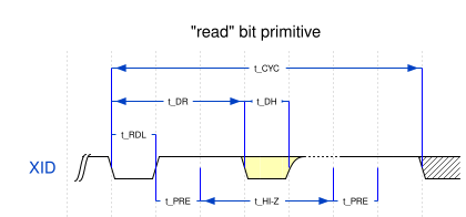
| Symbol | Parameter | Min. | Typ. | Max. | Units |
|---|---|---|---|---|---|
| tCYC | Cycle Time | 100 | - | - | µS |
| tRDL | Read Clock Low Time | 8 | 10 | 12 | µS |
| tPRE | ID Bus Precharge Time | 2 | - | - | µS |
| tHI-Z | Read Bit High Impedance Time | - | - | 40 | µS |
| tDR | Time to Data Ready | 20 | - | 26 | µS |
| tDH | Data Hold Time | 9 | - | 11 | µS |
| tW1L | Write "1" Low Time | 17 | 19 | 21 | µS |
| tW0L | Write "0" Low Time | 28 | 30 | 32 | µS |
| tRESETL | Reset Time Low | 43 | - | - | µS |
| tRESETH | Reset Time High | 200 | - | - | µS |
"reset" bit primitive
"reset" aborts all commands and instructs transducer to enter its initial state.
"read" bit primitive
The transducer's controller is attached to the signalling line via a bidirectional IO pin with a weak pull-up resistor. The controller's IO pin is in high impedance state. After receiving the "read" bit primitive, it becomes an output to drive the bus low as required.
"write 1" bit primitive
"write 0" bit primitive
Commands
The echosounder can issue four different commands. Bit order is LSB first.
| Command Mnemonic | Opcode | Address | Data Read Size |
|---|---|---|---|
| RESET | - | - | - |
| READ_VERSION | 0xCC | - | variable |
| READ_BYTE | 0x33 | 8bit address | 8 bit |
| READ_BLOCK | 0x99 | - | variable |
| CHECK_STATUS | - | - | 1 bit |
RESET command
RESET is issued as a bit primitive as described above.
READ_VERSION command
READ_VERSION is issued as Opcode 0xCC written to the slave.
Afterwards, a sequence of bytes is read with the first byte denoting the byte length of the available data.
READ_VERSION should be the first command after a RESET.
READ_BYTE command
READ_BYTE is issued as Opcode 0x33 and an 8 bit address written to the slave.
Valid addresses are 0..126, inclusive.
Afterwards, the result byte is clocked in.
READ_BLOCK command
READ_BLOCK is issued as Opcode 0x33.
Afterwards, a sequence of bytes is read with the first byte denoting the byte length of the available data. The last two bytes are a 16 bit checksum (big endian) using CRC-16-IBM algorithm.
CHECK_STATUS command
CHECK_STATUS is identical to the "read" bit primitive command.
If the transducer's processor is not able to respond, the bus will remain high during the read.
If the transducer's processor is waiting for a command, it answers the "read" bit primitive command by pulling the bus to low.
References
- ↑ 1.0 1.1 "Transducer identification" US patent 2005259517, issued 2005-11-24
- ↑ "Airmar Transducer ID Press Release". 2006-05-10. http://www.airmartechnology.com/uploads/pressrelease/xid%20release.pdf. "... enables the transducer to transmit important data to the echosounder, including transducer model, functions, frequency, power rating, beam pattern, impedance, ceramic element configuration and acoustic window material."
 |
 KSF
KSF


