Arc suppression
Topic: Physics
 From HandWiki - Reading time: 7 min
Arc suppression is the reduction of the electric arc[1][2][3][4][5] energy that occurs when current-carrying contacts are opened and closed. An electric arc is a man-made, continuous arc-discharge consisting of highly energized electrons and ions supported by an electric current of at least 100mA; not to be confused with an electric spark.[6]
Overview
Every time an electrical power device (for example: heaters, lamps, motors, transformers or similar power loads) turns on or off, its switch, relay or contactor transitions either from a CLOSED to an OPEN state ("BREAK") or from an OPEN to a CLOSED state ("MAKE"), under load, an electrical arc occurs between the two contact points (electrodes) of the switch.

The temperature of the resulting electric arc is very high (tens of thousands of degrees), causing the metal on the contact surfaces to melt, pool and migrate with the current. The high temperature of the arc causes dissociation of the surrounding gas molecules creating ozone, carbon monoxide, and other compounds. The arc energy slowly destroys the contact metal, causing some material to escape into the air as fine particulate matter. This very activity causes the material in the contacts to degrade quickly, resulting in device failure.[4][7]
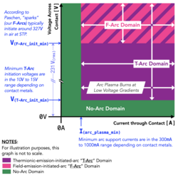
Understanding arc suppression requires an understanding of both arcing and arc initiation mechanisms. Contact arcs are either a Thermionic-Emission-Initiated-Arc ("T-Arc") or a Field-Emissions-Initiated-Arc ("F-Arc"), and are maintained by a continuous supply of power (think of an arc welder or a Xenon arc lamp).:
- The T-Arc is born out of Current and initiates around V(T-Arc_init_min), and the T-Arc plasma is maintained at or above the minimum-arc-current of I(arc_plasma_min).[8]
- The F-Arc is born out of Voltage and initiates around V(F-Arc_init_min), and the F-Arc plasma is maintained at or above the minimum-arc-current of I(arc_plasma_min).[8]
While arcing occurs during both the BREAK and MAKE transitions, the break arc is typically more energetic and thus more destructive.[8][9][10]

Arcing initiated during contact MAKE
During contact MAKE, F-Arc initiation occurs as the moving electrode nears the stationary electrode. Then the MAKE F-Arc plasma ignites and is promptly extinguished at the instant of contact impact. This initial impact results in a series of plasma pressure amplified MAKE bounces, with each bounce yielding a T-Arc. These bounces continue until the contact is micro-welded in the CLOSED position. (Note that "arc suppression" does not mean "arc elimination", as some tiny arcs ("arclets") yield beneficial micro-welds. These micro-welds are a desired and important power contact feature as they ensure vibration-resistant, low ohmic, and non-permanent electrode connections.)[8][9][10]

Arcing initiated during contact BREAK
The "BREAK Arc" consists of an initial BREAK T-Arc that may be extended by a series of BREAK F-arcs. The initial BREAK T-Arc is created after the explosion of the super-heated molten-metal bridge that had been carrying current as the contact begins to open. As the BREAK T-Arc plasma extinguishes and current is interrupted, inductance in the loop extends the duration of the "BREAK Arc" by initiating a series of BREAK F-Arcs which continue until the contact gap widens beyond the thermodynamic ability to support the burning plasma.[8][9][10]
Uses
There are several possible areas of use of arc suppression methods, among them metal film deposition and sputtering, electrostatic processes where electrical arcs are not desired (such as powder painting, air purification, and contact current arc suppression. In industrial, military and consumer electronic design, the latter method generally applies to devices such as electromechanical power switches, relays and contactors. In this context, arc suppression is contact protection.
Contact protection

Contact protection methods are designed to mitigate the wear and degradation occurring during the intended use of contacts within an electromechanical switch, relay or contactor and thus avoid an excessive increase in contact resistance or premature switch failure.
Arc suppression is an area of interest in engineering due to the destructive effects of the electrical arc to electromechanical power switches, relays and contactors' points of contact.[11] There are many forms of "arc suppression" that provide contact protection in applications operating at less than 1 Ampere. Most of these, however, are more accurately considered "transient suppression" and are therefore ineffective for either arc suppression or contact protection.[12][13]
Effectiveness

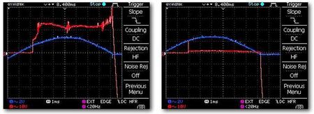
(left) Unsuppressed AC power electrical arc
(right) An identical arc with suppression.
The efficacy of an arc suppression solution for contact protection can be assessed using the Contact Arc Suppression Factor ("CASF")[14][15] to compare the calculated arc energy of the unsuppressed arc with that of the suppressed arc:
CASF = W(arc) / W(arclet)
Where W(arc) = Unsuppressed arc energy and W(arclet) = Suppressed arc energy. The unsuppressed and suppressed arc energy must be obtained graphically from oscilloscope measurements. The unsuppressed and suppressed arc energy is expressed in Watt seconds [Ws] or Joules [J]. The resulting Contact Arc Suppression Factor [CASF] is dimensionless.

W(arc) = V(arc) × I(arc) × T(arc)
Where V(arc): Arc burn voltage, I(arc): Arc burn current, is approximately I(load), where I(load) may be in the range from a few Ampere [A] to kilo Ampere [kA]; and T(arc): Arc burn duration, can be on the order of microseconds [μs] to seconds [s].
W(arclet) = V(arclet) × I(arclet) × T(arclet)
Where V(arclet): Arc ignition voltage, depending on the contact metal. E.g. about 12V for silver indium tin oxide; I(arclet): Arclet current, is approximately I(load) and may be in the range from a few Ampere [A] to kilo Ampere [kA]; and T(arclet): Arclet burn duration, is on the order of a few microseconds [μs].
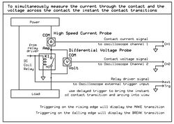
Electrical arcing across the contacts of an electromechanical relay may be effectively measured using an oscilloscope connected to a differential voltage probe across the relay contacts and a high speed current probe to measure the current through the contacts during operation under load.[14][15]
Alternatively, the electrical arc may also be visually observed on an electromechanical power switch, relay and contactor, with visible contacts, while the contacts are opening and closing under load.
Common devices
Common devices that may be reasonably effective arc suppressors in applications operating below 2 Amperes include capacitors, snubbers, diodes, Zener diodes, varistors, and transient voltage suppressors.[12][16][17] Contact arc suppression solutions that are considered effective in applications operating at more than 2 Amperes include:
- Electronic Power Contact Arc Suppressor
- Solid state relays are not electromechanical, have no contacts, and, thus, do not create electrical arcs.[18]
- Hybrid power relays
- Hybrid power contactors
Specialized devices

The circuit diagram is part of an issued patent for an electronic power contact arc suppressor intended to protect the contacts of electrical relays or contactors. It suppresses arcs by providing an alternate path around contacts as they open or close. [19][20]
Some contact arc suppressors operate connected solely across the protected contact, while other contact arc suppressors are also connected to the coil of the contactor to provide the suppressor with additional input about contact operation.
Benefits of arc suppression
Arc suppression techniques can produce a number of benefits:[20]
- Minimized contact damage from arcing and therefore reduced maintenance, repair and replacement frequency.
- Increased contact reliability.
- Reduced heat generation resulting in less heat management measures such as venting and fans.
- Reduced ozone and pollutant emissions.
- Reduced electromagnetic interference (EMI) from arcs - a common source of radiated EMI.
See also
References
- ↑ "Electric arc". TheFreeDictionary.com. http://www.thefreedictionary.com/Electrical+arcing.
- ↑ Martin, T. L. (n.d.). "Electric arcing". http://www.elr-electrical.co.za/Electrical%20arcing.html.
- ↑ Howatson, A. M. (1976). An Introduction to Gas Discharges (second ed.). Oxford: Pergamon Press. pp. 47–101. ISBN 9780080205755.
- ↑ 4.0 4.1 "Contact Arc Phenomenon". http://www.multi-contact.com.sg/elesta/images/Technical%20Information.pdf.
- ↑ Thorbus, Robert; Henke, Reinhold (2021-01-01). "THE ARC SPECIES ZOO; Arcs Are Self-feeding Plasma Burning Monsters; Sparks Are Not". AST Academic Poster #4 of 16. https://www.academia.edu/74815850/THE_ARC_SPECIES_ZOO_Arcs_Are_Self_feeding_Plasma_Burning_Monsters_Sparks_Are_Not.
- ↑ Thorbus, Robert; Henke, Reinhold (2021-01-01). "ARCS VS. SPARKS; What's The Deal?". AST Academic Poster #3 of 16. https://www.academia.edu/74815610/ARCS_VS_SPARKS_Whats_The_Deal.
- ↑ Martin 1999, p. 1.3
- ↑ 8.0 8.1 8.2 8.3 8.4 Thorbus, Robert; Henke, Reinhold (2021-01-01). "ABOUT CONTACT ARC INITIATIONS; No Inductance-In-The-Loop Required!". AST Academic Poster #12 of 16. https://www.academia.edu/74820189/ABOUT_CONTACT_ARC_INITIATIONS_No_Inductance_In_The_Loop_Required_.
- ↑ 9.0 9.1 9.2 The National Association of Relay Manufacturers, Engineers' Relay Handbook, NARM, 8th Edition, 1980, pg 245
- ↑ 10.0 10.1 10.2 Martin, Perry L. (1999). Electronic Failure Analysis Handbook. McGraw-Hill. pp. 16.1–16.29.
- ↑ Tyco P&B, Contact ARC Phenomenon, Tyco Electronics Corporation – P&B, Winston-Salem, NC, Application Note 13C3203, pgs. 1-3
- ↑ 12.0 12.1 Thorbus, Robert; Henke, Reinhold (2021-01-01). "WHAT IS ARC SUPPRESSION? Three Historical Interpretations and Our Findings". AST Academic Poster #5 of 16. https://www.academia.edu/90199738/WHAT_IS_ARC_SUPPRESSION_Three_Historical_Interpretations_and_Our_Findings.
- ↑ Thorbus, Robert; Henke, Reinhold (2021-01-01). "THE RC-SNUBBER, Redesigned". AST Academic Poster #6 of 16. https://www.academia.edu/74817305/THE_RC_SNUBBER_Redesigned.
- ↑ 14.0 14.1 "Arc Suppression Factor | Arc Suppression Technologies". https://arcsuppressiontechnologies.com/get-smart-about-the-arc-2/arc-suppression-factor/.
- ↑ 15.0 15.1 Henke, Reinhold; Thorbus, Robert. "POWER CONTACT ARC SUPPRESSION; How Effective are Snubbers?". https://www.academia.edu/74815000/POWER_CONTACT_ARC_SUPPRESSION_How_Effective_are_Snubbers.
- ↑ Tyco P&B, Relay Contact Life, Tyco Electronics Corporation – P&B, Winston-Salem, NC, Application Note 13C3236, pgs. 1-3
- ↑ Henke, Reinhold; Thorbus, Robert (2021-05-01). "FACTS & MYTHS OF ARC SUPPRESSION; Bringing Clarity to Address the Uncertainty and Confusion". https://www.academia.edu/74817595/FACTS_and_MYTHS_OF_ARC_SUPPRESSION_Bringing_Clarity_to_Address_the_Uncertainty_and_Confusion.
- ↑ The National Association of Relay Manufacturers, Engineers' Relay Handbook, NARM, 8th Edition, 1980, Chapter 13
- ↑ , Reinhold"Two terminal arc suppressor" patent US8619395B2, issued 2013-12-31, assigned to Arc Suppression Technologies.
- ↑ 20.0 20.1 "Features & Benefits Arc Suppression". http://www.electronic-components.com.au/products-services/arc-suppression/.
Further reading
- Relays - Frequently Asked Questions
- Arc suppression articles on Institute of Electrical and Electronics Engineers website
 |
 KSF
KSF