Combustion instability
Topic: Physics
 From HandWiki - Reading time: 8 min
Combustion instabilities are physical phenomena occurring in a reacting flow (e.g., a flame) in which some perturbations, even very small ones, grow and then become large enough to alter the features of the flow in some particular way.[1][2][3]

In many practical cases, the appearance of combustion instabilities is undesirable. For instance, thermoacoustic instabilities are a major hazard to gas turbines and rocket engines.[1] Moreover, flame blowoff of an aero-gas-turbine engine in mid-flight is clearly dangerous (see flameout).
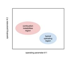
Because of these hazards, the engineering design process of engines involves the determination of a stability map (see figure). This process identifies a combustion-instability region and attempts to either eliminate this region or moved the operating region away from it. This is a very costly iterative process. For example, the numerous tests required to develop rocket engines [4] are largely in part due to the need to eliminate or reduce the impact of thermoacoustic combustion instabilities.
Classification of combustion instabilities
In applications directed towards engines, combustion instability has been classified into three categories, not entirely distinct. This classification was first introduced by Marcel Barrère and Forman A. Williams in 1969.[5] The three categories are[6]
- Chamber instabilities - instabilities arising due to the occurrence of combustion inside a chamber (acoustic instabilities, shock instabilities, fluid-dynamic instabilities associated with the chamber, etc.,)
- Intrinsic instabilities - instabilities arising irrespective of whether combustion occurs inside a chamber or not (chemical-kinetic instabilities, diffusive-thermal instabilities, hydrodynamic instabilities such as Darrieus–Landau instability, Rayleigh–Taylor instability etc.,)
- System instabilities - instabilities arising due to the interaction between combustion processes in the chamber and anywhere else in the system (feed-system interactions, exhaust-system interactions, etc.,)
Thermoacoustic combustion instabilities
In this type of instabilities the perturbations that grow and alter the features of the flow are of an acoustics nature. Their associated pressure oscillations can have well defined frequencies with amplitudes high enough to pose a serious hazard to combustion systems.[1] For example, in rocket engines, such as the Rocketdyne F-1 rocket engine [7] in the Saturn V program, instabilities can lead to massive damage of the combustion chamber and surrounding components (see rocket engines). Furthermore, instabilities are known to destroy gas-turbine-engine components during testing.[8] They represent a hazard to any type of combustion system.
Thermoacoustic combustion instabilities can be explained by distinguishing the following physical processes:
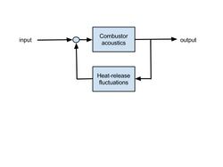
- the feedback between heat-release fluctuations (or flame fluctuations) with the combustor or combustion chamber acoustics
- the coupling of these two processes in space-time
- the strength of this coupling in comparison with acoustic losses
- the physical mechanisms behind the heat-release fluctuations
The simplest example of a thermoacoustic combustion instability is perhaps that happening in a horizontal Rijke tube (see also thermoacoustics): Consider the flow through a horizontal tube open at both ends, in which a flat flame sits at a distance of one-quarter the tube length from the leftmost end. In a similar way to an organ pipe, acoustic waves travel up and down the tube producing a particular pattern of standing waves. Such a pattern also forms in actual combustors, but takes a more complex form.[9] The acoustic waves perturb the flame. In turn, the flame affects the acoustics. This feedback between the acoustic waves in the combustor and the heat-release fluctuations from the flame is a hallmark of thermoacoustic combustion instabilities. It is typically represented with a block diagram (see figure). Under some conditions, the perturbations will grow and then saturate, producing a particular noise. In fact, it is said that the flame of a Rijke tube sings.

The conditions under which perturbations will grow are given by Rayleigh's (John William Strutt, 3rd Baron Rayleigh) criterion:[10] Thermoacoustic combustion instabilities will occur if the volume integral of the correlation of pressure and heat-release fluctuations over the whole tube is larger than zero (see also thermoacoustics). In other words, instabilities will happen if heat-release fluctuations are coupled with acoustical pressure fluctuations in space-time (see figure). However, this condition is not sufficient for the instability to occur.
Another necessary condition for the establishment of a combustion instability is that the driving of the instability from the above coupling must be larger than the sum of the acoustic losses.[11] These losses happen through the tube's boundaries, or are due to viscous dissipation.
Combining the above two conditions, and for simplicity assuming here small fluctuations and an inviscid flow, leads to the extended Rayleigh's criterion. Mathematically, this criterion is given by the next inequality:
Here p' represents pressure fluctuations, q' heat release fluctuations, velocity fluctuations, T is a long enough time interval, V denotes volume, S surface, and is a normal to the surface boundaries. The left hand side denotes the coupling between heat-release fluctuations and acoustic pressure fluctuations, and the right hand side represents the loss of acoustic energy at the tube boundaries.

Graphically, for a particular combustor, the extended Rayleigh's criterion is represented in the figure on the right as a function of frequency. The left hand side of the above inequality is called gains, and the right hand side losses. Notice that there is a region where the gains exceeds the losses. In other words, the above inequality is satisfied. Furthermore, note that in this region the response of the combustor to acoustic fluctuations peaks. Thus, the likelihood of a combustion instability in this region is high, making it a region to avoid in the operation of the combustor. This graphical representation of a hypothetical combustor allows to group three methods to prevent combustion instabilities:[1] increase the losses; reduce the gains; or move the combustor's peak response away from the region where gains exceed losses.
To clarify further the role of the coupling between heat-release fluctuations and pressure fluctuations in producing and driving an instability, it is useful to make a comparison with the operation of an internal combustion engine (ICE). In an ICE, a higher thermal efficiency is achieved by releasing the heat via combustion at a higher pressure. Likewise, a stronger driving of a combustion instability happens when the heat is released at a higher pressure. But while high heat release and high pressure coincide (roughly) throughout the combustion chamber in an ICE, they coincide at a particular region or regions during a combustion instability. Furthermore, whereas in an ICE the high pressure is achieved through mechanical compression with a piston or a compressor, in a combustion instability high pressure regions form when a standing acoustic wave is formed.
The physical mechanisms producing the above heat-release fluctuations are numerous.[1][8] Nonetheless, they can be roughly divided into three groups: heat-release fluctuations due to mixture inhomogeneities; those due to hydrodynamic instabilities; and, those due to static combustion instabilities. To picture heat-release fluctuations due to mixture inhomogeneities, consider a pulsating stream of gaseous fuel upstream of a flame-holder. Such a pulsating stream may well be produced by acoustic oscillations in the combustion chamber that are coupled with the fuel-feed system. Many other causes are possible. The fuel mixes with the ambient air in a way that an inhomogeneous mixture reaches the flame, e.g., the blobs of fuel-and-air that reach the flame could alternate between rich and lean. As a result, heat-release fluctuations occur. Heat-release fluctuations produced by hydrodynamic instabilities happen, for example, in bluff-body-stabilized combustors when vortices interact with the flame (see previous figure).[12] Lastly, heat-release fluctuations due to static instabilities are related to the mechanisms explained in the next section.
Static instability or flame blow-off

Static instability [2] or flame blow-off refer to phenomena involving the interaction between the chemical composition of the fuel-oxidizer mixture and the flow environment of the flame.[13] To explain these phenomena, consider a flame that is stabilized with swirl, as in a gas-turbine combustor, or with a bluff body. Moreover, say that the chemical composition and flow conditions are such that the flame is burning vigorously, and that the former is set by the fuel-oxidizer ratio (see air-fuel ratio) and the latter by the oncoming velocity. For a fixed oncoming velocity, decreasing the fuel-oxidizer ratio makes the flame change its shape, and by decreasing it further the flame oscillates or moves intermittently. In practice, these are undesirable conditions. Further decreasing the fuel-oxidizer ratio blows-off the flame. This is clearly an operational failure. For a fixed fuel-oxidizer ratio, increasing the oncoming velocity makes the flame behave in a similar way to the one just described.

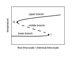
Even though the processes just described are studied with experiments or with Computational Fluid Dynamics, it is instructive to explain them with a simpler analysis. In this analysis, the interaction of the flame with the flow environment is modeled as a perfectly-mixed chemical reactor.[14] With this model, the governing parameter is the ratio between a flow time-scale (or residence time in the reactor) and a chemical-time scale, and the key observable is the reactor's maximum temperature. The relationship between parameter and observable is given by the so-called S-shape curve (see figure). This curve results from the solution of the governing equations of the reactor model. It has three branches: an upper branch in which the flame is burning vigorously, i.e., it is "stable"; a middle branch in which the flame is "unstable" (the probability for solutions of the reactor-model equations to be in this unstable branch is small); and a lower branch in which there is no flame but a cold fuel-oxidizer mixture. The decrease of the fuel-oxidizer ratio or increase of oncoming velocity mentioned above correspond to a decrease of the ratio of the flow and chemical time scales. This in turn corresponds to a movement towards the left in the S-shape curve. In this way, a flame that is burning vigorously is represented by the upper branch, and its blow-off is the movement towards the left along this branch towards the quenching point Q. Once this point is passed, the flame enters the middle branch, becoming thus "unstable", or blows off. This is how this simple model captures qualitatively the more complex behavior explained in the above example of a swirl or bluff-body-stabilized flame.
Intrinsic flame instabilities
In contrast with thermoacoustic combustion instabilities, where the role of acoustics is dominant, intrinsic flame instabilities refer to instabilities produced by differential and preferential diffusion, thermal expansion, buoyancy, and heat losses. Examples of these instabilities include the Darrieus–Landau instability, the Rayleigh-Taylor instability, and thermal-diffusive instabilities (see Double diffusive convection).
References
- ↑ 1.0 1.1 1.2 1.3 1.4 1.5 Culick, F. E. and Kuentzmann, P. (2006). Unsteady Motions in Combustion Chambers for Propulsion Systems. NATO Research and Technology Organization.
- ↑ 2.0 2.1 Lieuwen, T. C. (2012). Unsteady Combustor Physics. Cambridge University Press.
- ↑ Matalon, M. (2007). "Intrinsic flame instabilities in premixed and nonpremixed combustion". Annual Review of Fluid Mechanics 39 (1): 163–191. doi:10.1146/annurev.fluid.38.050304.092153. Bibcode: 2007AnRFM..39..163M.
- ↑ Pempie, P. and Vernin, H.. "Liquid rocket engine test plan comparison". AIAA Paper 2001-3256.
- ↑ Barrere, M., & Williams, F. A. (1969, January). Comparison of combustion instabilities found in various types of combustion chambers. In Symposium (International) on Combustion (Vol. 12, No. 1, pp. 169-181). Elsevier.
- ↑ Williams, Forman A. Combustion theory. CRC Press, 2018.
- ↑ Oefelein, J. C.; Yang, V. (1993). "Comprehensive review of liquid-propellant combustion instabilities in F-1 engines". Journal of Propulsion and Power 9 (5): 657–677. doi:10.2514/3.23674. Bibcode: 1993JPP.....9..657O.
- ↑ 8.0 8.1 Lieuwen, T. C.; Yang, V. (2005). Combustion instabilities in gas turbine engines. AIAA.
- ↑ Poinsot, T. and Veynante, D. (2005). Theoretical and numerical combustion. RT Edwards.
- ↑ Rayleigh, J. W. S. (1896). The Theory of Sound Volume 2. Dover Publications.
- ↑ Nicoud, F. and Poinsot, T. (2005). "Thermoacoustic instabilities: Should the Rayleigh criterion be extended to include entropy changes?". Combustion and Flame 142 (1–2): 153–159. doi:10.1016/j.combustflame.2005.02.013. https://hal.archives-ouvertes.fr/hal-00908285/file/chu-CandF-final.pdf.
- ↑ Schadow, K. C. and Gutmark, E. (1992). "Combustion instability related to vortex shedding in dump combustors and their passive control". Progress in Energy and Combustion Science 18 (2): 117–132. doi:10.1016/0360-1285(92)90020-2.
- ↑ Glassman, I. and Yetter, R. A. and Glumac, N. G. (2014). Combustion. Academic Press.
- ↑ Peters, N. (2000). Turbulent Combustion. Cambridge University Press.
 |
 KSF
KSF