Instrumentation in petrochemical industries
Topic: Physics
 From HandWiki - Reading time: 11 min
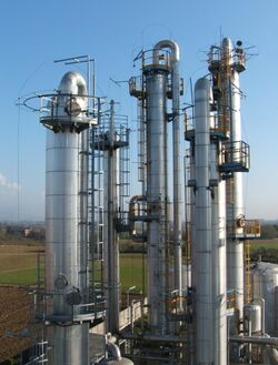
Instrumentation is used to monitor and control the process plant in the oil, gas and petrochemical industries. Instrumentation ensures that the plant operates within defined parameters to produce materials of consistent quality and within the required specifications. It also ensures that the plant is operated safely and acts to correct out of tolerance operation and to automatically shut down the plant to prevent hazardous conditions from occurring. Instrumentation comprises sensor elements, signal transmitters, controllers, indicators and alarms, actuated valves, logic circuits and operator interfaces.
An outline of key instrumentation is shown on Process Flow Diagrams (PFD) which indicate the principal equipment and the flow of fluids in the plant. Piping and Instrumentation Diagrams (P&ID) provide details of all the equipment (vessels, pumps, etc), piping and instrumentation on the plant in a symbolic and diagrammatic form.
The elements of instrumentation
Instrumentation includes sensing devices to measure process parameters such as pressure, temperature, liquid level, flow, velocity, composition, density, weight; and mechanical and electrical parameters such as vibration, position, power, current and voltage.[1]
- The measured value of a parameter is displayed and recorded locally and/or in a control room. If the measured variable exceeds pre-defined limits an alarm warns the operating personnel of a potential problem. Automatic executive action is taken by the instrumentation to close or open shutdown valves and dampers, or to trip (stop) pumps and compressors, to move the plant to a safe condition.[2]
- Correct operation of the petrochemical process plant is achieved through the action of control loops.[1] These automatically maintain and control the pressure, temperature, liquid level and flowrate of fluid in vessels and piping. Control loops compare the measured value of a parameter on the plant, eg. pressure, with a pre-determined set point. A difference between the measured variable and the set point generates a signal which modulates the position of a control valve (the final element) to maintain the measured variable at the set point.
- Valves are actuated by an electric motor, hydraulic fluid or air. For air-operated control valves, electrical signals from the control system are converted to an air pressure for the valve actuator in a current/pneumatic I/P converter. Upon loss of pneumatic or hydraulic pressure valves may fail to an open (FO) or fail to a closed (FC) position.
- Some instrumentation is self actuating. For example, pressure regulators maintain a constant pre-set pressure, and rupture discs and pressure safety valves open at pre-set pressures.[3]
- Instrumentation includes facilities for operating personnel to intervene in the plant either locally or from a control room. Personnel can open or close valves, change set points, start and stop pumps or compressors, and over-ride shutdown functions (in specific controlled circumstances such as during start-up).[1]
Temperature instrumentation
Oil, gas and petrochemical processes are undertaken at specific temperatures.
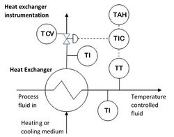
- Measurement of temperature of fluids in the petrochemical industry is undertaken by temperature elements (TE). These can be Thermocouples or Platinum Resistance Temperature Detectors (RTDs). The latter are used for their good temperature response. Local temperature indicators (TI) are located on the inlet and outlet streams of heat exchangers to monitor the performance of the exchanger.[4]
- In industrial applications gaseous or liquid fluids may be heated or cooled. This duty is undertaken in a heat exchanger, whereby the fluid is heated or cooled by heat transfer with a second fluid such as water, glycol, hot oil or another process fluid (the heating or cooling medium).[5][4] Temperature control is used to maintain the desired temperature of the first fluid. A temperature sensor transmitter (TT) is located in the first fluid at its outlet from the heat exchanger. This measured temperature is fed to the temperature controller (TIC) where it is compared to the desired set point temperature. The output of the controller, which is related to the difference between the measured variable and the set point, is fed to a control valve (TCV) in the second fluid to adjust the flow of the heating or cooling medium.[1] In the case of a fluid being cooled, if the temperature of the fluid rises the temperature controller acts to open the TCV increasing the flow of the cooling medium which increases the heat transfer and reduces the temperature of the first fluid. Conversely if the temperature falls the controller acts to close the TCV which reduces the heat transfer increasing the temperature of the first fluid. In the case of heating medium with the falling temperature of the first fluid the controller would act to open the TCV to increase the flow of heating medium thereby raising the temperature of the first fluid. The controller (TIC) may also generate high (TAH) and low temperature (TAL) alarms to warn operating personnel of a potential problem.[4]
- Fin fan coolers use air to cool gases and liquids.[6] The temperature of fluid is controlled (TIC) by opening or closing dampers on the cooler or adjusting the speed of the fan or the pitch angle of the fan blades thereby increasing or decreasing the flow of air.
- Temperature monitoring and control instrumentation is used in fired heaters and furnaces to adjust the fuel flow valve (FCV) to maintain a desired thermal output.[7] Waste heat recovery units (WHRU) are used to extract heat from the flow of hot exhaust gases from a gas turbine to heat a fluid (heating medium). Instrumentation includes controllers to maintain a desired temperature of the heating medium by closing or opening dampers in the exhaust gas flow.
- Low temperature alarms (TSL) are used where cold fluids could be routed to pipework which is not suitable for cold service. Instrumentation may include an initial alarm (TAL) and then a shutdown action (TSLL) to close a shutdown valve (XV).
- Temperature sensors (TE) are used to indicate that plant flares have been unintentionally extinguished (BAL), perhaps due to insufficient flowrate of gases to maintain a flame.[8]
Pressure instrumentation
Oil, gas and petrochemical processes are undertaken at specific operating pressures.
- Pressure is measured by pressure sensors (PE) which send pressure (PT) signals to pressure controllers (PIC). Pressure vessels and tanks are fitted with local pressure indicators (PI).
- In the petrochemical industry pressure is controlled by maintaining a constant pressure in the upper gas space of a vessel.[1][9][4] A pressure controller (PIC) adjusts the setting on a pressure control valve (PCV) that feeds gas forward to the next stage of the process. A rising pressure in the vessel results in the PCV opening to feed more gas forward. If the pressure continues to rise some controllers then act to open a second PCV that feeds excess gas to the flare system. The pressure transmitter is configured to provide warning alarms (PAL and PAH) if the pressure exceeds set high and low limits. If these limits are exceeded (PALL and PAHH) an automatic shutdown of the system is initiated which includes closure of the inlet valves of the vessel.[2] The pressure sensor (PT) that initiates a shutdown is a separate instrument loop from the PT associated with the pressure control loop to mitigate common mode failures and to ensure greater reliability of the shutdown function.[1]
- The operation of hydrocyclones is controlled by pressure instrumentation that maintains fixed differential pressures between the inlet and the oil and water outlets.[4]
- Turbo-expanders are controlled by maintaining the inlet pressure (PIC) at a constant value by controlling the angle of the expander inlet vanes. A split range pressure controller may also modulate a Joule-Thomson valve across the turbo-expander.[10][4]
- Pressure in blanketed tanks is maintained by self actuating pressure control valves (PCVs). As liquid is withdrawn from the tank the pressure in the gas space falls. The blanket gas supply valve opens to maintain the pressure. As the tank fills with liquid the pressure rises and a vent gas valve open to vent gas to atmosphere or a vent system.[11]
- Rupture (bursting) discs (PSE) and pressure relief or pressure safety valves (PSV) are important pressure control devices.[3] Both are self-actuating and are designed to open at a preset pressure to provide an essential safety function on the petrochemical plant.[8]
Flow instrumentation
The throughput of a petrochemical plant is measured and controlled by flow instrumentation.
- Flow measuring devices devices (FE) include vortex, positive displacement (PD),[12] differential pressure (DP),[13] coriolis, ultrasonic,[14] and rotameters.
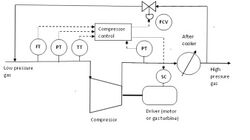
- The flow through compressors, see schematic, is controlled by measuring the flow (FT) through the machine at the suction and controlling the speed (SC) of the prime mover (electric motor or gas turbine) that is driving the compressor.[4] Anti-surge control ensures a minimum flow of fluid through the compressor. The flow (FT) at the discharge and measurements of the suction and discharge pressures (PT) and temperatures (TT) of the fluid flowing through the compressor are measured. The anti-surge controller (FIC) modulates a control valve (FCV) which recycles cooled gas from downstream of the compressor after-cooler back to the suction of the compressor. Low flow alarms (FAL) provide a warning indication to operating personnel.[10]
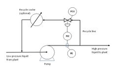
- Large process pumps are provided with minimum flow protection.[4] This comprises measurement of flow (FE) at the pump discharge, this measurement is an input to a flow controller (FIC) whose set point is the minimum flow required through the pump(see diagram). As the flow reduces to the minimum flow value the controller acts to open a flow control valve (FCV) to recycle fluid from the discharge back to the suction of the pump.[15]
- Flow metering (FIQ) is required where custody transfer of fluids takes place, such as an outgoing pipeline or at a tanker loading station. Accurate measurement of the flow is essential and parameters such as liquid density are measured.[16]
- Flare and vent systems are purged to prevent air ingress and the formation of potentially explosive mixtures.[17] The flowrate of purge gas is set by rotameter (FIC) or fixed orifice plate (FO). A low flow alarm (FAL) warns operating personnel that the purge flow has reduced significantly.[8]
- Pipelines are monitored by measuring the flowrate of fluid at each end, a discrepancy (FDA) may indicate a leak in the pipeline.
Level instrumentation
The level measurement of liquids in pressure vessels and tanks in the petrochemical industry is undertaken by differential pressure level meters, radar, magnetostrictive, nucleonic, magnetic float and pneumatic bubbler instruments.[1][9]
- Level instrumentation determines the height of liquids by measuring the position of a gas/liquid or liquid/liquid interface within the vessel or tank. Such interfaces include oil/gas, oil/water, condensate/water, glycol/condensate, etc. Local indication (LI) includes sight glasses which show the liquid level directly through a vertical glass tube attached to the vessel/tank.
- Phase interfaces are maintained at a constant level by level transmitters (LT) transmitting a signal to a level controller (LIC) which compares the measured value with the desired set point. The difference is sent as a signal to a level control valve (LCV) on the liquid outlet from the vessel. As the level rises the controller acts to open the valve to draw off liquid to reduce the level. Similarly as the levels fall the controller acts to close the LCV to reduce outflow of fluid.[4]
- Some vessels store liquid until it is pumped out. The controller (LIC) acts to start and stop the pump within a specified band. For example, start the pump when the level rises to 0.6m, stop the pump when the level falls to 0.4m.
- High and low level alarms (LAH and LAL) warn operating personnel that levels are outside predefined limits. Further deviation (LAHH and LALL) initiates a shutdown either to close emergency shutdown valves (ESDV) on the inlet to the vessel or on the liquid outlet lines.[2] As with high and low pressure instrumentation the shutdown function comprises an independent measurement loop to prevent a common mode failure. Loss of liquid level in the vessel may lead to gas blowby where high pressure gas flows to the downstream vessel through the liquid outlet line. The structural integrity of the downstream vessel can be compromised. In addition high liquid level in the vessel may lead to carryover of liquid into the gas outlet may damage downstream equipment such as gas compressors.
- High liquid level in a flare drum can lead to undesirable carryover of liquid to the flare.[8] A high-high liquid level (LSHH) in the flare drum initiates a plant shutdown.
- One of the problems with a significant number of technologies is that they are installed through a nozzle and are exposed to products. This can create several problems, especially when retrofitting new equipment to vessels that have already been stress relieved, as it may not be possible to fit the instrument at the location required. Also, as the measuring element is exposed to the contents within the vessel, it may either attack or coat the instrument causing it to fail in service. One of the most reliable methods for measuring level is using a Nuclear gauge, as it is installed outside the vessel and doesn't normally require a nozzle for bulk level measurement. The measuring element is installed outside the process and can be maintained in normal operation without taking a shutdown. Shutdown is only required for an accurate calibration.
Analyser instrumentation
A wide range of analysis instruments are used in the oil, gas and petrochemical industries.[1][16]
- Chromatography – to measure the quality of product or reactants
- Density (oil) – for custody metering of liquids
- Dewpoint (water dewpoint and hydrocarbon dewpoint) to check the efficiency of dehydration or dewpoint control plant
- Electrical conductivity – to measure the effectiveness of potable water reverse osmosis plant
- Oil-in-water – prior to discharge of water into the environment
- pH of reactants and products
- Sulphur content – to check the efficiency of gas sweetening plant
Most instruments function continuously and provide a log of data and trends. Some analyser instruments are configured to alarm (AAH) if a measurement reaches a critical level.
Other instrumentation
- Major pumps and compressors are provided with vibration sensors (VT) to give operating personnel a warning (VA) of potential mechanical problems with the machine.[15][10]
- Rupture discs (PSE) and pressure safety valves (PSV) are self-actuated and provide no immediate indication that they have ruptured or lifted.[3] Instrumentation such as pressure alarms (PXA) or movement alarms (PZA) may be fitted to indicate that they have operated.[8]
- Corrosion coupons and corrosion probes provide a local indication of corrosion rates of fluids flowing in piping.
- Pipeline pig launchers and receivers are provided with a pig signaller (XA) to indicate that a pig has been launched or has arrived.[4]
- Packaged items of equipment (compressors, diesel engines, electricity generators, etc) are fitted with local vendor supplied instrumentation. When equipment malfunctions a multivariable signal (UA) is sent to the control room.
- The fire and gas detection system comprises local sensors to detect the presence of gas, smoke or fire. These initiate alarms in the control room. Simultaneous detection of multiple sensors initiates action to start firewater pumps and close fire dampers in enclosed spaces.
- The petrochemical plant may have several levels of shutdown. A unit shutdown (USD) entails shutdown of one limited unit with the rest of the plant remaining in operation. A production shutdown (PSD) entails shutdown of the entire process plant. An emergency shutdown (ESD) entails complete shutdown of the plant.
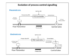
- Older plant may have local control loops which operate pneumatic (3 – 15 psia) final element actuators. Sensors may also transmit electrical signals (4 – 20mA). Conversion between pneumatic and electrical signals is undertaken by P/I and I/P converters. Control of modern plant is based on a distributed control systems using fieldbus digital protocols.
See also
- Control engineering
- Instrument and control engineering
- Functional safety
- Safety integrity level
- Oil refinery
- Piping and instrumentation diagram
- Process flow diagram
- Process manufacturing
References
- ↑ 1.0 1.1 1.2 1.3 1.4 1.5 1.6 1.7 Gas Processors Suppliers Association (2004). Engineering Data Book. Tulsa, Oklahoma: GPSA. pp. Section 4 Instrumentation.
- ↑ 2.0 2.1 2.2 "Recommended Practice 14C for Analysis, Design, Installation, and Testing of Basic Surface Safety Systems for Offshore Production Platforms". American Petroleum Institute. 2007. https://law.resource.org/pub/us/cfr/ibr/002/api.14c.2001.pdf.
- ↑ 3.0 3.1 3.2 American Petroleum Institute, Recommended Practice API RP 520 Sizing, Selection, and Installation of Pressure-Relieving Devices in Refineries
- ↑ 4.0 4.1 4.2 4.3 4.4 4.5 4.6 4.7 4.8 4.9 P&IDS NW Hutton 1988
- ↑ GPSA (2004). Engineering Data Book. Tulsa, Oklahoma: GPSA. pp. Section 9 Heat Exchangers.
- ↑ GPSA (2004). Engineering Data Book. Tulsa, Oklahoma: GPSA. pp. Section 10 Aircooled Exchangers.
- ↑ GPSA (2004). Engineering Data Book. Tulsa, Oklahoma: GPSA. pp. Section 8 Fired Equipment.
- ↑ 8.0 8.1 8.2 8.3 8.4 GPSA (2004). Engineering Data Book. Tulsa, Oklahoma: GPSA. pp. Section 5 Relief Systems.
- ↑ 9.0 9.1 GPSA (2004). Engineering Data Book. Tulsa, Oklahoma: GPSA. pp. Section 7 Separation Equipment.
- ↑ 10.0 10.1 10.2 GPSA (2004). Engineering Data Book. Tulsa, Oklahoma: GPSA. pp. Section 13 Compressors and Expanders.
- ↑ GPSA (2004). Engineering Data Book. Tulsa, Oklahoma: GPSA. pp. Section 6 Storage.
- ↑ Alan S Morris (9 March 2001). Measurement and Instrumentation Principles. Butterworth-Heinemann. pp. 328–. ISBN 978-0-08-049648-1. https://books.google.com/books?id=qPi-SSchB6MC&pg=PA328.
- ↑ Roger C. Baker (9 August 2002). An Introductory Guide to Flow Measurement. John Wiley & Sons. pp. 52–. ISBN 978-1-86058-348-3. https://books.google.com/books?id=XDi9MSfLqoAC&pg=PA52.
- ↑ Lipták, Béla G. (27 June 2003). Instrument Engineers' Handbook: Process measurement and analysis. Taylor & Francis, Inc.. pp. 151 (Chapter 2). ISBN 978-0-8493-1083-6. https://books.google.com/books?id=a05NAvaqfcUC&q=petrochemical+flow+meter&pg=PA352.
- ↑ 15.0 15.1 GPSA (2004). Engineering Data Book. Tulsa, Oklahoma: GPSA. pp. Section 12 Pumps and Hydraulic Turbines.
- ↑ 16.0 16.1 GPSA (2004). Engineering Data Book. Tulsa, Oklahoma: GPSA. pp. Section 3 Measurement.
- ↑ American Petroleum Institute, Recommended Practice RP 521 Guide for Pressure-Relieving and Depressuring Systems
 |
 KSF
KSF