Wavefront
 From HandWiki - Reading time: 6 min
In physics, the wavefront of a time-varying wave field is the set (locus) of all points having the same phase.[1] The term is generally meaningful only for fields that, at each point, vary sinusoidally in time with a single temporal frequency (otherwise the phase is not well defined).
Wavefronts usually move with time. For waves propagating in a unidimensional medium, the wavefronts are usually single points; they are curves in a two dimensional medium, and surfaces in a three-dimensional one.


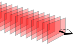
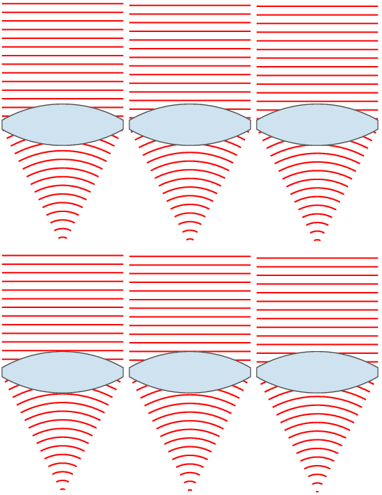
For a sinusoidal plane wave, the wavefronts are planes perpendicular to the direction of propagation, that move in that direction together with the wave. For a sinusoidal spherical wave, the wavefronts are spherical surfaces that expand with it. If the speed of propagation is different at different points of a wavefront, the shape and/or orientation of the wavefronts may change by refraction. In particular, lenses can change the shape of optical wavefronts from planar to spherical, or vice versa.
In classical physics, the diffraction phenomenon is described by the Huygens–Fresnel principle that treats each point in a propagating wavefront as a collection of individual spherical wavelets.[2] The characteristic bending pattern is most pronounced when a wave from a coherent source (such as a laser) encounters a slit/aperture that is comparable in size to its wavelength, as shown in the inserted image. This is due to the addition, or interference, of different points on the wavefront (or, equivalently, each wavelet) that travel by paths of different lengths to the registering surface. If there are multiple, closely spaced openings (e.g., a diffraction grating), a complex pattern of varying intensity can result.
Simple wavefronts and propagation
Optical systems can be described with Maxwell's equations, and linear propagating waves such as sound or electron beams have similar wave equations. However, given the above simplifications, Huygens' principle provides a quick method to predict the propagation of a wavefront through, for example, free space. The construction is as follows: Let every point on the wavefront be considered a new point source. By calculating the total effect from every point source, the resulting field at new points can be computed. Computational algorithms are often based on this approach. Specific cases for simple wavefronts can be computed directly. For example, a spherical wavefront will remain spherical as the energy of the wave is carried away equally in all directions. Such directions of energy flow, which are always perpendicular to the wavefront, are called rays creating multiple wavefronts.[3]

The simplest form of a wavefront is the plane wave, where the rays are parallel to one another. The light from this type of wave is referred to as collimated light. The plane wavefront is a good model for a surface-section of a very large spherical wavefront; for instance, sunlight strikes the earth with a spherical wavefront that has a radius of about 150 million kilometers (1 AU). For many purposes, such a wavefront can be considered planar over distances of the diameter of Earth.
Wavefronts travel with the speed of light in all directions in an isotropic medium.
Wavefront aberrations
Methods using wavefront measurements or predictions can be considered an advanced approach to lens optics, where a single focal distance may not exist due to lens thickness or imperfections. For manufacturing reasons, a perfect lens has a spherical (or toroidal) surface shape though, theoretically, the ideal surface would be aspheric. Shortcomings such as these in an optical system cause what are called optical aberrations. The best-known aberrations include spherical aberration and coma.[4]
However, there may be more complex sources of aberrations such as in a large telescope due to spatial variations in the index of refraction of the atmosphere. The deviation of a wavefront in an optical system from a desired perfect planar wavefront is called the wavefront aberration. Wavefront aberrations are usually described as either a sampled image or a collection of two-dimensional polynomial terms. Minimization of these aberrations is considered desirable for many applications in optical systems.
Wavefront sensor and reconstruction techniques
A wavefront sensor is a device which measures the wavefront aberration in a coherent signal to describe the optical quality or lack thereof in an optical system. There are many applications that include adaptive optics, optical metrology and even the measurement of the aberrations in the eye itself. In this approach, a weak laser source is directed into the eye and the reflection off the retina is sampled and processed. Another application of software reconstruction of the phase is the control of telescopes through the use of adaptive optics.
Mathematical techniques like phase imaging or curvature sensing are also capable of providing wavefront estimations. These algorithms compute wavefront images from conventional brightfield images at different focal planes without the need for specialised wavefront optics. While Shack-Hartmann lenslet arrays are limited in lateral resolution to the size of the lenslet array, techniques such as these are only limited by the resolution of digital images used to compute the wavefront measurements. That said, those wavefront sensors suffer from linearity issues and so are much less robust than the original SHWFS, in term of phase measurement.
There are several types of wavefront sensors, including:
- Shack–Hartmann wavefront sensor: a very common method using a Shack–Hartmann lenslet array.
- Phase-shifting Schlieren technique
- Wavefront curvature sensor: also called the Roddier test. It yields good correction but needs an already good system as a starting point.
- Pyramid wavefront sensor
- Common-path interferometer
- Foucault knife-edge test
- Multilateral shearing interferometer
- Ronchi tester
- Shearing interferometer
Although an amplitude splitting interferometer such as the Michelson interferometer could be called a wavefront sensor, the term is normally applied to instruments that do not require an unaberrated reference beam to interfere with.
See also
- Huygens-Fresnel principle
- Wavefront sensor
- Adaptive optics
- Deformable mirror
- Wave field synthesis
- Hamilton–Jacobi equation
References
- ↑ Essential Principles of Physics, P. M. Whelan, M. J. Hodgeson, 2nd Edition, 1978, John Murray, ISBN 0-7195-3382-1
- ↑ Wireless Communications: Principles and Practice, Prentice Hall communications engineering and emerging technologies series, T. S. Rappaport, Prentice Hall, 2002 pg 126
- ↑ University Physics – With Modern Physics (12th Edition), H. D. Young, R. A. Freedman (Original edition), Addison-Wesley (Pearson International), 1st Edition: 1949, 12th Edition: 2008, ISBN 0-321-50130-6, ISBN 978-0-321-50130-1
- ↑ Encyclopaedia of Physics (2nd Edition), R.G. Lerner, G.L. Trigg, VHC publishers, 1991, ISBN (Verlagsgesellschaft) 3-527-26954-1, ISBN (VHC Inc.) 0-89573-752-3
Further reading
Textbooks and books
- Concepts of Modern Physics (4th Edition), A. Beiser, Physics, McGraw-Hill (International), 1987, ISBN 0-07-100144-1
- Physics with Modern Applications, L. H. Greenberg, Holt-Saunders International W. B. Saunders and Co, 1978, ISBN 0-7216-4247-0
- Principles of Physics, J. B. Marion, W. F. Hornyak, Holt-Saunders International Saunders College, 1984, ISBN 4-8337-0195-2
- Introduction to Electrodynamics (3rd Edition), D. J. Griffiths, Pearson Education, Dorling Kindersley, 2007, ISBN 81-7758-293-3
- Light and Matter: Electromagnetism, Optics, Spectroscopy and Lasers, Y. B. Band, John Wiley & Sons, 2010, ISBN 978-0-471-89931-0
- The Light Fantastic – Introduction to Classic and Quantum Optics, I. R. Kenyon, Oxford University Press, 2008, ISBN 978-0-19-856646-5
- McGraw Hill Encyclopaedia of Physics (2nd Edition), C. B. Parker, 1994, ISBN 0-07-051400-3
- Arnold, V. I. (1990). Singularities of Caustics and Wave Fronts. Mathematics and Its Applications. 62. Dordrecht: Springer Netherlands. doi:10.1007/978-94-011-3330-2. ISBN 978-1-4020-0333-2. OCLC 22509804. http://link.springer.com/10.1007/978-94-011-3330-2.
Journals
- Arnol'd, V. I. (1983). "Особенности систем лучей" (in Russian). Успехи математических наук 38 (2(230)): 77–147. doi:10.1070/RM1983v038n02ABEH003471. http://www.mathnet.ru/links/57fe8d94a41dde5a389a743bce14b776/rm7160.pdf.
- François Roddier, Claude Roddier (April 1991). "Wavefront reconstruction using iterative Fourier transforms". Applied Optics 30 (11): 1325–1327. doi:10.1364/AO.30.001325. ISSN 0003-6935. PMID 20700283. Bibcode: 1991ApOpt..30.1325R.
- Claude Roddier, François Roddier (November 1993). "Wave-front reconstruction from defocused images and the testing of ground-based optical telescopes". Journal of the Optical Society of America A 10 (11): 2277–2287. doi:10.1364/JOSAA.10.002277. Bibcode: 1993JOSAA..10.2277R.
- Shcherbak, O. P. (1988). "Волновые фронты и группы отражений" (in Russian). Успехи математических наук 43 (3(261)): 125–160. doi:10.1070/RM1988v043n03ABEH001741. http://www.mathnet.ru/links/100d8a1eb447dd5b7afb5374163c5c3d/rm1892.pdf.
- Wavefront tip/tilt estimation from defocused images
External links
- LightPipes – Free Unix wavefront propagation software
- AO Tutorial: Wave-front Sensors
- Wavefront sensing: Establishments Research groups and companies with interests in wavefront sensing and adaptive optics.
 |
 KSF
KSF