Blisk
 From Wikipedia - Reading time: 5 min

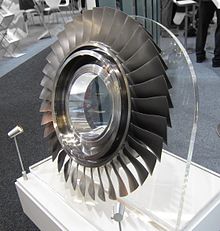
A blisk (portmanteau of bladed disk) is a turbomachine component comprising both rotor disk and blades as a single part instead of a disk assembled with individual removable blades. Blisks generally have better aerodynamics than conventional rotors with single blades and are lighter. They may be additively manufactured, integrally cast, machined from a solid piece of material, or made by welding individual blades to a rotor disk. The term is used mainly in aerospace engine design. Blisks may also be known as integrally bladed rotors (IBR).
History
[edit]Blisk manufacturing has been used since the mid-1980s. It was first used by Sermatech-Lehr (now known as GKN Aerospace[1]) in 1985 for the compressors of the T700 helicopter engine. Since then, its use has continued to increase in major applications for both compressors and fan blade rotors. Examples include the Rocketdyne RS-68 rocket engine and the General Electric F110 turbofan.
The F-35B variant of the Joint Strike Fighter uses blisks to achieve short take-off and vertical landing.[2]
Engine manufacturer CFM International is using blisk technology in the compressor section of its LEAP-X demonstrator engine program, which has completed full-scale rig testing.[3] PowerJet SaM146 engines used on Sukhoi Superjet 100s are also equipped with blisks.[4]
General Electric's Passport (formerly "TechX") engine uses blisks for both its main 52" fan as well as for 5 of its 10 high pressure compressor stages.[5][6] The GEnx already uses blisks in some stages.
Advantages
[edit]
Instead of making bare compressor disks and attaching the blades later, blisks are single elements combining the two. This eliminates the need to attach the blades to the disk (via screws, bolts, etc.), thus decreasing the number of components in the compressor, while at the same time decreasing drag and increasing efficiency of air compression in the engine. The elimination of the dovetail attachment found on traditional turbine blades eliminates a source for crack initiation and subsequent propagation.[7]
Efficiency improvements of up to 8% are possible.[8]
Disadvantages
[edit]Any damage to integrally bladed rotor blades beyond minor dents requires the full removal of the engine so that the rotor may be replaced or, if possible, replacement blades welded on. Maintenance of this nature cannot be done on the flightline and often must be performed at a specialized facility. Integrally bladed rotor blades must undergo rigorous harmonic vibration testing as well as dynamic balancing to an extremely high standard, since the natural damping of the dovetail attachment of a typical turbine blade is no longer present.[7]
Process
[edit]General
[edit]Blisks can be produced with several different manufacturing processes, including CNC milling, investment casting, electro chemical machining, 3D printing, or welding. Research is being conducted to produce them using friction welding of "near net" part shapes that are then machined down to the final blisk shape.[9]
Measurement and inspection
[edit]
The measurement and inspection of blisks is crucial for guaranteeing engine performance carried out at the end of the manufacturing processes. Traditionally this has been achieved using tactile devices, like coordinate-measuring machines (CMM), but as geometries and requirements increase, the trend in modern factories is to carry out 3D scanning inspection systems.[10] This has advantages of the speed of measurement compared to tactile devices, whilst collecting 3D data to relate back to design characteristics. Using 3D data, parts can be catalogued in this way, often called digital twin, allowing monitoring of the product through its life-cycle.
Blisk repair using adaptive machining
[edit]Engine-run blisks pose their own set of unique requirements. After parts have been in service in the engine, noticeable amounts of damage and wear will be observed. Provided that the damage and wear are within thresholds set by the design authority, it is possible that the blisks can be repaired.
Repair of blisk components is complex and first requires an accurate 3D representation of the component. The quickest way to do this is by 3D scanning the product.[10] After the part is scanned, an STL file (stereolithograph) can be passed to a CNC code generating software such as NX CAM. The tool paths are regenerated to suit the measured geometry and not the nominally generated CAD in a process known as adaptive machining.[11]
The processes would typically involve removing part or all of a blade(s), followed by a weld back to approximate size before finishing by final machining back to the airfoil shape.[12]
References
[edit]- ^ GKN Aerospace.
- ^ Zolfagharifard, Ellie (28 March 2011), "Rolls-Royce's LiftSystem for the Joint Strike Fighter", The Engineer, archived from the original on 19 December 2013, retrieved 18 April 2011.
- ^ "Optioning the Future", Aviation Week & Space Technology, vol. 170, no. 10, p. 37, 9 March 2009.
- ^ Burchell, Bill (2 November 2010), "Powering Up Next-Gen Engine MRO", Aviation Week[permanent dead link].
- ^ "GE Aviation Freezes Design of Passport Engine" (Press release). GE Aviation. 2012-05-13. Retrieved 2022-05-13..
- ^ "type certificate data sheet E00091EN, revision 0" (PDF). FAA. 29 April 2016.
- ^ a b Younossi, O; et al. (2002), Military Jet Acquisition: Technology Basics and Cost-Estimating Methodology, RAND Corporation, pp. 29–30, ISBN 0-8330-3282-8.
- ^ Croft, John (21 October 2010), "NBAA: GE TechX fan blisk is all the buzz", Flightglobal.com.
- ^ "Metallics Make Comeback With Manufacturing Advances", Aviation Week, Jun 5, 2013, archived from the original on April 27, 2015, retrieved February 23, 2022.
- ^ a b "Blisk Measurement & Inspection using GOM, ATOS 5 for Airfoil, 3D Scanners". Archived from the original on 2020-10-29.
- ^ "Overview of an Adaptive Machining Process". Archived from the original on 2016-07-25.
- ^ "Rolls-Royce Blisk Repair Process". Archived from the original on 2021-01-11.
External links
[edit]- LiftFan blisk, Rolls-Royce, March 2003[permanent dead link].
- Facts, Rolls-Royce, archived from the original on 2006-10-19.
- Media, Rolls-Royce, archived from the original on 2006-09-21.
 KSF
KSF