Flow Visualization
 From Citizendium
 Flow visualization, as the name suggests, is the process of making the motion of fluids visible and thereby elucidating the physics of the motion. In experiments flow visualization is achieved mainly by the injection of visible material (smoke in air, dye or tiny bubbles in water) into the flow. With the increasing importance of flow simulations using computers (computational fluid dynamics), illustrating the flow with the help of computer graphics has become a main branch of flow visualization. Flow visualization aims at helping scientists and engineers understand the physics and characteristics of fluid flows. The images that flow visualization produces often have great aesthetic value along with their scientific content.
Experimental flow visualization[edit]
As mentioned, the most important technique for visualizing flow in real experiments is injecting material into the fluid and observing how this material is advected by the flow. The material injected can be of different kinds but should generally be sufficiently inert not to disrupt the flow. Smoke is often used to visualize gas flow, air bubbles can be injected into water to show vortical motion, and dye can be used to illustrate the flow behavior of most liquids. In geophysical flows in oceanography and meteorology one has to rely on naturally occurring markers, such as clouds, plankton, pollutants (including oil slicks) to produce flow visualization.
Computer graphics[edit]
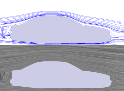
The illustration of flow by computer graphics can be applied to any flow which is available in the form of measured or simulated data. The data can consist of different quantities such as velocity, pressure or density. Each of these quantities can be visualized by a certain type of graphical representation. Most experimental techniques can be imitated using simulation data. Traces of particles, for example, can be computed mathematically and the resulting curves drawn as lines or curves on the display. In addition special features such as lines representing centers of vortices ("vortex core lines") can be derived mathematically from the given quantities. Drawing these features can further aid the understanding of the flow characteristics.
Flow visualization techniques[edit]
- Streamlines: a curve that is everywhere tangent to the particle velocity; coincides with particle traces in steady flow.
- Pathlines: particle traces in both steady and unsteady flow.
- Streaklines: lines consisting of particles released continuously from a stationary or moving source point (e.g., a point on a moving body) into the flow.
- Time lines: lines consisting of particles released simultaneously into the flow.
- Streamsurface: in steady flow, a continuum of traces of particles released into the flow from a line source (continuum of streamlines).
- Pathsurface: continuum of traces of particles released into a steady or unsteady flow from a line (continuum of pathlines).
- Surface oil flow: the body of an object immersed in a flow is covered with oil. The flow leaves streaks in the oil which depict the flow structure on the surface of the object. This technique can be imitated by line integral convolution (LIC) on computers.
Categories: [Suggestion Bot Tag]
↧ Download as ZWI file | Last modified: 08/17/2024 17:14:21 | 3 views
☰ Source: https://citizendium.org/wiki/Flow_visualization | License: CC BY-SA 3.0

 KSF
KSF