Lock
 From Britannica 11th Edition (1911)
 Lock (from the O. Eng. loc.; the word appears, in different forms, in many Teutonic languages, but with such various meanings as “hole,” Ger. Loch, “lid,” Swed. lock, &c.; probably the original was a root meaning “to enclose”), a fastening, particularly one which consists of a bolt held in a certain position by one or more movable parts which require to be placed in definite positions by the aid of a key or of a secret arrangement of letters, figures or signs, before the bolt can be moved. It is with such fastenings that the present article chiefly deals.
The word is also used, in the original sense of an enclosure or barrier, for a length of water in a river or canal, or at the entrance of a dock, enclosed at both ends by gates, the “lock-gates,” and fitted with sluices, to enable vessels to be raised from a lower to a higher level or vice versa (see Canal and Dock). In guns and rifles the lock is the mechanism which effects the firing of the charge; it thus appears in the names of old types of weapons, such as wheel-lock, match-lock, flint-lock (see Arms and Armour, § Firearms; also Gun and Rifle). Lock (Ger. Locke) in the sense of a curl or tuft of hair, the separate groups in which the hair naturally grows, may be, in ultimate origin, connected with the root of the main word. Lockjaw is the popular name of the disease known as tetanus (q.v.). The name “Lock Hospital” is frequently used in English for a hospital for patients suffering from venereal diseases. According to the New English Dictionary there was in Southwark as early as 1453 a leper-hospital, known as the Lock Lazar House, which later was used for the treatment of venereal diseases. The name appears to have become used in the present sense as early as the end of the 17th century. Lock hospitals were established in London in 1745-1747 and in Dublin in 1754-1755.
 |
| Fig. 1. |
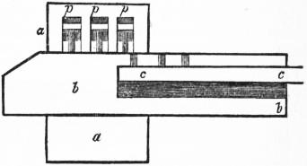
The forms in which locks are manufactured, such as padlock, rim-lock, mortise-lock, one-sided or two-sided, &c., are necessarily extremely numerous; and the variations in the details of construction of any one of these forms are still more numerous, so that it is impossible to do more here than describe the main types which have been or are in common use. Probably the earliest locks were of Chinese origin. Specimens of these still extant are quite as secure as any locks manufactured in Europe up to the 18th century, but it is impossible to ascertain the date of their manufacture. With the exception, in all probability, of these Chinese examples, the earliest lock of which the construction is known is the Egyptian, which was used four thousand years ago. In fig. 1, aa is the body of the lock, bb the bolt and cc the key. The three pins p, p, p drop into three holes in the bolt when it is pushed in, and so hold it fast; and they are raised again by putting in the key through the large hole in the bolt and raising it a little, so that the pins in the key push the locking pins up out of the way of the bolt. It was evidently to locks and keys of this nature that the prophet alluded: “And the key of the house of David will I lay upon his shoulder” (Isaiah xxii. 22), the word muftah used in this passage being the common word for key to this day.
 |
 |
| Fig. 2. | Fig. 3. |
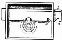
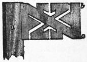
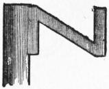
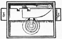
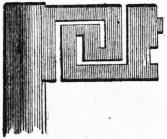
In the 18th century the European lock was nothing better than a mere bolt, held in its place, either shut or open, by a spring b (fig. 2), which pressed it down, and so held it at either one end or the other of the convex notch aa; and the only impediment to opening it was the wards which the key had to pass before it could turn in the keyhole. But it was always possible to find the shape of the wards by merely putting in a blank key covered with wax, and pressing it against them; and when this had been done it was unnecessary to cut out the key into the complicated form of the wards (such as fig. 3), because no part of that key does any work except the edge bc farthest from the pipe a; and so a key of the form fig. 4 would do just as well. Thus a small collection of skeleton keys, as they are called, of a few different patterns, was all the stock in trade that a lock-picker required.
 |
 |
| Fig. 4. | Fig. 5. |
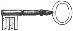
The common single-tumbler lock (fig. 5) requires two operations instead of one to open it. The tumbler at turns on a pivot at t, and has a square pin at a, which drops into a notch in the bolt bb, when it is either quite open or quite shut, and the tumbler Lever locks. must be lifted by the key before the bolt can be moved again. The tumbler offered little resistance to picking, as the height to which it might be lifted was not limited and the bolt would operate provided only that this height was sufficient; the improvement which formed the foundation of the modern key lock was the substitution of what is known as the “lever” for the tumbler, the difference being that the lever must be lifted to exactly the right height to allow the bolt to pass. This improvement, together with the obvious one of using more than one lever, was introduced in 1778 by Robert Barron, and is illustrated in figs. 6 and 7. Unless the square pin a (fig. 6) is lifted by the key to the proper height and no higher, the bolt cannot move. Fig. 8 illustrates the key of such a lock with four levers, the different distances between the centre of the key barrel and the edge of the bit being adapted to lift the levers to the respective heights required. This lock differs from the modern lever lock only in the fact that Barron made his gating in the bolt and carried stumps on his levers, instead of having the main stump riveted into the bolt and the gatings in the levers as is the modern practice.
 |
 |
| Fig. 6. | Fig. 7. |
 |
| Fig. 8. |
A lock operating on exactly the same principle but entirely different in construction (fig. 9) was invented by Joseph Bramah in 1784. It consists of an outer barrel aaaa, within which is a revolving barrel, cccc, held in place by a steel disk, dd, and provided with a pin b fixed eccentrically for operating the bolt; the barrel is prevented from turning by sheet metal sliders ss, which slide axially in radial grooves in the barrel and project into slots cut into the steel disk which is fastened to the case of the lock. Each slider has a gating cut in its outer edge sufficiently deep to allow it to embrace the inwardly projecting steel plate and turn on it with the barrel. The key is of tubular form having slots cut in its end, each of a depth corresponding to the position of the gating in one of the sliders; so that, on inserting the key, each slider is pushed in—against a spring—exactly far enough to bring its slot opposite the steel disk; in this position the barrel carrying the sliders is turned by the key and actuates the bolt.
 |
| Fig. 9. |
Up to 1851 it was generally believed that well-made lever locks of all types were practically unpickable, but at this time Alfred Charles Hobbs—an American—demonstrated, by picking the locks of Barron, Chubb, Bramah and others, that this belief was a fallacy. The method of Hobbs became widely known as the “tickling” or “tentative” method. In the modern lever lock the bolt carries a projecting piece—the “main stump”—which, when the levers are all raised to the proper height, enters the slots—“gatings”—in their faces. If, when the levers are not in this position, pressure is applied to the bolt, the main stump will press against the face of the levers; but owing to inaccuracies of workmanship and other causes the pressure will not be equal on all the levers. If now, the pressure on the bolt being maintained, each lever in turn is carefully raised a little, one will be found on which the pressure of the stump is greatest; this one is lifted till it becomes easy and then carefully lowered till it is sustained by the pressure of the stump in a new position. Another lever now bears the greatest pressure, and this in its turn is similarly treated. By this gradual or “tentative” process the levers will in time all be raised to the correct height and the bolt will slip back without, if sufficient care has been exercised, any of the levers having been raised above its correct position. Although this method of picking only became generally known in 1851, it is evident that it was not novel, since in 1817 one of Bramah’s workmen, named Russell, invented the use of false notches or gatings, which were slots similar to the true gating but of small depth cut in the face of the levers. Similar false gatings were used in Anthony Radford Strutt’s lock in 1819. The only possible object of these gatings—two of which are shown in each of the sliders of Bramah’s lock—was to prevent the tentative method of picking. They are, however, not efficient for their purpose although they render the operation more difficult and tedious.
 |
| Fig. 10. |
The best-known locks up to 1851 were those of Jeremiah Chubb, their popularity being due to their superior workmanship and probably still more to their title “detector.” His lock, patented in 1818, contained a device intended to frustrate attempts at picking, and further to detect if such an attempt had been made. This device, at any rate as far as detecting was concerned, had been anticipated by the patent of Thomas Ruxton in 1816. Since the device only comes into operation when any lever is raised too high, it is not effective against a skilful application of the tentative method. The original form of this lock is shown in fig. 10, when the lever DT, which turns on a pin in the middle, is acted upon at its end T by a spring S, which will evidently allow some play to the lever on either side of the corner X; but the moment it is pushed past that point the spring will carry it farther in the same direction, like what is called in clock-work a jumper. In its proper position that end always remains above the turning-point; but, if any one of the tumblers is raised too high, the other end D of the detector, which reaches over all the levers, is lifted so far that the end T is sent down below the corner, and the tooth T then falls into a notch in the bolt, and so prevents it from being drawn back, even though all the levers are raised properly by the right key. It thus at once becomes obvious that somebody has been trying to pick the lock. The way to open it, then, is to turn the key the other way, as if to overlock the bolt; a short piece of gating near the end of the levers allows the bolt to advance just far enough to push the tooth of the detector up again by means of its inclination there, and then the lock can be opened as usual. To render the mechanism of locks more inaccessible for picking purposes, two devices, the “curtain” and the “barrel,” were in use; these devices were simply the one a disk and the other a cylinder carrying a keyhole which revolved with the key and so closed the fixed keyhole in the case.
 |
| Fig. 11. |
It is to Hobbs himself that we are indebted for the invention of the movable stump, since called the safety lever, the only device introduced rendering the tentative method of picking inoperative. This invention was incorporated in the “protector” locks of Hobbs, Hart & Co.; it consists in the employment of a movable main stump which is not riveted into the bolt as usual, but is set on the end b of a bent lever abc (fig. 11) which lies in a hollow of the bolt A behind it, turning on a pivot in the bolt itself, and kept steady by a small friction-spring e. The stump comes through a hole in the bolt large enough to let it have a little play; and the long end a of the lever stands just above the edge of a square pin d, which is fixed in the back plate of the lock. When the lock is locked, if the bolt be pushed back, no sensible pressure on the levers is produced, but only just enough to turn this protector lever, as Hobbs called it, on its pivot c, and so bring down its end a in front of the square pin, and then the bolt can no more be pushed back than when held by Chubb’s detector. The protector is set free again by merely pushing the bolt forward with the key, without reference to the levers. However, the protector could be prevented from acting by a method used by the inventor himself for another purpose, viz., by pushing a piece of watch-spring through the keyhole, and up behind the bolt, so as to reach the protector at a, and keep it up while the bolt was pushed back, or, again, by pushing up the watch-spring between any two of the levers, and holding the end b of the protector with it, so as to press the stump against the levers. Both these devices, however, are prevented now by letting in a feather FF in a groove between the bolt and the back of the lock, which no watch-spring can pass, and also bringing a piece of the feather forward through the front gating of the levers just under the stump. In this form the lock is safe against any mode of picking known. A lock possessing valuable features was invented in 1852 by Sir Edmund Beckett—afterwards Lord Grimthorpe—but did not come into general use for commercial reasons.
All the locks containing many levers so far described have a common defect in that the levers are moved in one direction by the key and in the other by springs. But it not infrequently happens that dirt or grease gets between the levers and causes two or more to stick together, in which case one of them is lifted too high and the bolt is prevented from operating. To overcome this difficulty locks, especially those intended for safes, have been made so that alternate levers move in opposite directions, the key having two bits on opposite sides. This construction entails that the key enter the body of the levers instead of passing below them, an arrangement that had previously been in use to reduce the space into which gunpowder could be packed through the keyhole.
 |
| Fig. 12. |
The key locks chiefly used in English safes have been the ordinary lever lock with 6-8 or 10 levers, Chubb’s “detector,” Hobbs’s “protector” or variants of these. In the Yale lock, which reverts in some degree to the idea of the ancient Egyptian Key locks. lock, America has produced one key lock which has come into almost universal use in that country and is certainly worthy of note. The key of this lock, shown full size at ka in fig. 12, is remarkably small, being stamped from a piece of flat steel and weighing only a small fraction of an ounce. The barrel abc has to turn, as in the Bramah lock, in order to move the bolt, which is not shown in the figure. That may be done either as in Bramah locks or by a tongue or bit attached to the end ab of the barrel as in several other locks. The barrel is prevented from being turned, except by the proper key, thus. The (apparently) five plugs with spiral springs over them in fig. 12 are really all divided at the cross line bc, being all now lifted to the proper height by the key. Consequently the barrel abc can turn round, as there is no plug either projecting from it or projecting into it. But when the key is out, all the plugs are pushed down by the springs, and so the upper ones descend into the barrel and hold it fast. And again, if any of the steps of a false key are too high, some of the lower plugs will be pushed up beyond the barrel into the holes above them, and so the barrel cannot turn. The bevelled end of the key near a enables it to be pushed in under the plugs, though with some friction and resistance.
It is frequently convenient to have a number of different locks so arranged that, whilst each has its own individual key, yet one special or “master” key will operate any of the series. In warded locks this is done by “differing” the wards of the individual locks so that each key will only pass its own lock, and then filing away the bit of an extra key so that it will pass all the wards; the objection to this method is that any of the individual keys can easily be filed away and so form a master key. A better method, which meets this objection, consists in making all the levers except one—or if need be two—of each lock alike and cutting another gating or widening the gating in the differing levers, so as to pass the master key which has one—or two—special steps.
The growth of safe deposits has called for special locks so that when a box changes tenants the outgoing tenant’s key shall be useless. In some cases the lock has been taken off and another substituted, but this is a clumsy makeshift now rarely employed, and has been superseded by the use of changeable key locks.
 |
| Fig. 13. |
The first of these, invented by Robert Newell in 1841, was introduced into Great Britain from America by Hobbs in 1851. A simpler form, the construction of which is clearly shown by fig. 13, was brought out by Hobbs, Hart & Co. The bolt of this lock, instead of the ordinary main stump, carries a set of sliders, PPS, one corresponding to each lever and each carrying a projection S corresponding to a portion of the main stump. It will be seen that if any key having steps of certain lengths is inserted when the lock is unlocked and the bolt B thrown thereby, each slider will be raised to a height corresponding to that to which its lever is raised by the key, and the two fixed teeth CC will engage two of the teeth in the front of each slider, so that they will be held in place ready to enter the lever gatings when the same key is inserted.
 |
| Fig. 14. |
A changeable key lock introduced by the Chatwood Safe Co. has no gatings in the levers, whose fronts are cut with teeth gearing into similar teeth cut in a set of disks carrying the gatings. The disks are mounted on a stud which can be moved by a key from the back of the lock in such a way that while the main stump is in the gatings—keeping the disks in position—the disks are carried forward out of gear with the levers; the key can then be removed and another having steps of suitable length inserted and turned so as to raise the levers, the disks being then brought back into gear.
 |
| Fig. 15. |
Both the above locks require that the key steps should have certain definite lengths corresponding to the teeth, but a later lock resembling to some extent that brought out by Hobbs, Hart & Co. has been introduced by the Chatwood Co., in which it is sufficient after unlocking the lock to file any of the key steps and so alter the pattern of the key in any way. In this lock, which is illustrated in fig. 14, unlike all those that have been described, the levers are not pivoted but slide upon guide stumps; the main stump is divided as in Hobbs Hart’s lock, the various pieces being clamped together by a screw to form a solid stump. The sliders composing the main stump are not provided with teeth, the changing being effected as follows: when the bolt is partly shot by the correct key, the screw which binds the sliders together as it comes opposite an opening in the back of the case is loosened, the key is removed and altered—or a fresh key substituted—and is inserted so as to lift the levers to their correct height and expose the clamping screw at the back, which is then tightened. This lock is now commonly used for safe deposits, combined with a small lever lock of which the custodian carries the key, and which either blocks the bolt of the main lock or covers the keyhole.
In connexion with changeable key locks requiring key steps of definite lengths, much ingenuity has been displayed in designing keys with movable bits or steps, as fig. 15, which are useful chiefly as duplicates, being built up to match the key from time to time in use, and then deposited in some bank or other secure place to be used in case of emergency.
From the very earliest times secret devices, either to hide keyholes or to take the place of locks proper, have been in use; these are to-day only seriously represented by “combination” locks which, whilst following the same Combination locks. general principles as key locks, differ entirely in construction. Locks in which the arranging of the internal parts in their proper positions was secured by the manipulation of external parts marked with letters or numbers were common in China in very early times, but their history is unfortunately lost. This form of lock has been developed to a very high degree of perfection and is, for safes, in almost universal use to-day in America.
The American lock consists of a series of disks mounted upon one spindle, only one, however—the bolt disk—being fixed thereto, and provided each with a gating into which a stump connected with the bolt can drop when all the gatings lie upon a given line parallel to the axis of the spindle. Each disk is provided with a driving pin so arranged that it can impinge on and drive a similar pin in its next neighbour; the gating in the bolt disk and the portion of the stump which enters it are so formed that the disk can draw the bolt back. The spindle is provided on the outside with a knob and graduated disk—usually with 100 divisions—surrounded by an annulus on which a fixed position is denoted. Each disk, including the bolt disk, is provided with a pin projecting from its surface in such a way that the pin of one disk comes into contact with that of the next disk and drives it round. If, then, the bolt disk being at the back, there are three letter disks and the spindle is rotated to the left, the bolt disk will in the course of one revolution pick up letter disk No. 1—counting from the bolt disk—in the second revolution it will pick up No. 2, and in the third No. 3, the revolution being continued for part of a turn till the number corresponding to the correct position of No. 3 is reached. The revolution of the spindle is now reversed. The bolt disk leaves No. 1 in the first revolution and picks it up again, and the second revolution picks up No. 2. The motion is continued for part of a revolution till No. 2 is brought to the correct position (No. 3 obviously not being disturbed) and is then reversed. No. 1 is again left behind and picked up in the first revolution to the left, the motion being continued till the correct position of No. 1 is reached, when, on reversal, the gating in the bolt disk comes into the correct position, the stump falls and a continuance of the motion to the right draws back the bolt. A lock constructed in this way would be of little utility, as the combination would have to be determined once for all by the maker. The difficulty is got over by making the letter disks in two parts, the inner part carrying the driving pin and the outer the gating; these two parts are locked together by small cams or other devices which come into such a position that they can be released with the help of a square key when the lock is unlocked. The combination is set by altering the position of the inner disks with the driving pins in relation to the outer part carrying the gatings which are meanwhile held steady by the square key.
One advantage of the combination lock is that there is no key to be lost or stolen, but the means adopted by burglars, especially in America, are such that even this is not a perfect protection, cases having occurred in which a person Time locks. has been compelled to disclose the combination. With key locks the keyhole through the safe door forms a distinct point of danger, and with combination locks the spindle passing through the door may be attacked by explosives. To obviate these two risks time locks were introduced in America and have been used in Europe. Essentially the time lock consists of a high-class chronometer or watch movement, little liable to get out of order, driving a disk provided with a gating such that the bolt can only enter the gating during certain hours; as a rule two, three or four chronometers are used, any one of which can release the lock.
The Yale time lock contains two chronometer movements which revolve two dial plates studded with twenty-four pins to represent the twenty-four hours of the day. These pins, when pushed in, form a track on which run rollers supporting the lever which secures the bolt or locking agency, but when they are drawn out the track is broken, the rollers fall down and the bolt is released. By pulling out the day pins, say from 9 till 4, the door is automatically prepared for opening between these hours, and at 4 it again of itself locks up. For keeping the repository closed over Sundays and holidays, a subsidiary segment or track is brought into play by which a period of twenty-four hours is added to the locked interval. Careful provision is made against the eventuality of running down or accidental stoppage of the clock motion, by which the rightful owner might be as seriously incommoded as the burglar. In the Yale lock, just before the chronometers run out, a trigger is released which depresses the lever by which the bolt is held in position.
↧ Download as ZWI file | Last modified: 11/17/2022 15:24:04 | 36 views
☰ Source: https://oldpedia.org/article/britannica11/Lock | License: Public domain in the USA. Project Gutenberg License
 ZWI signed:
 KSF
KSF